ComNav P4 Installation and Operation
Document PN 29010100 V1r0 - 58 -
Rudder Angle Indicators
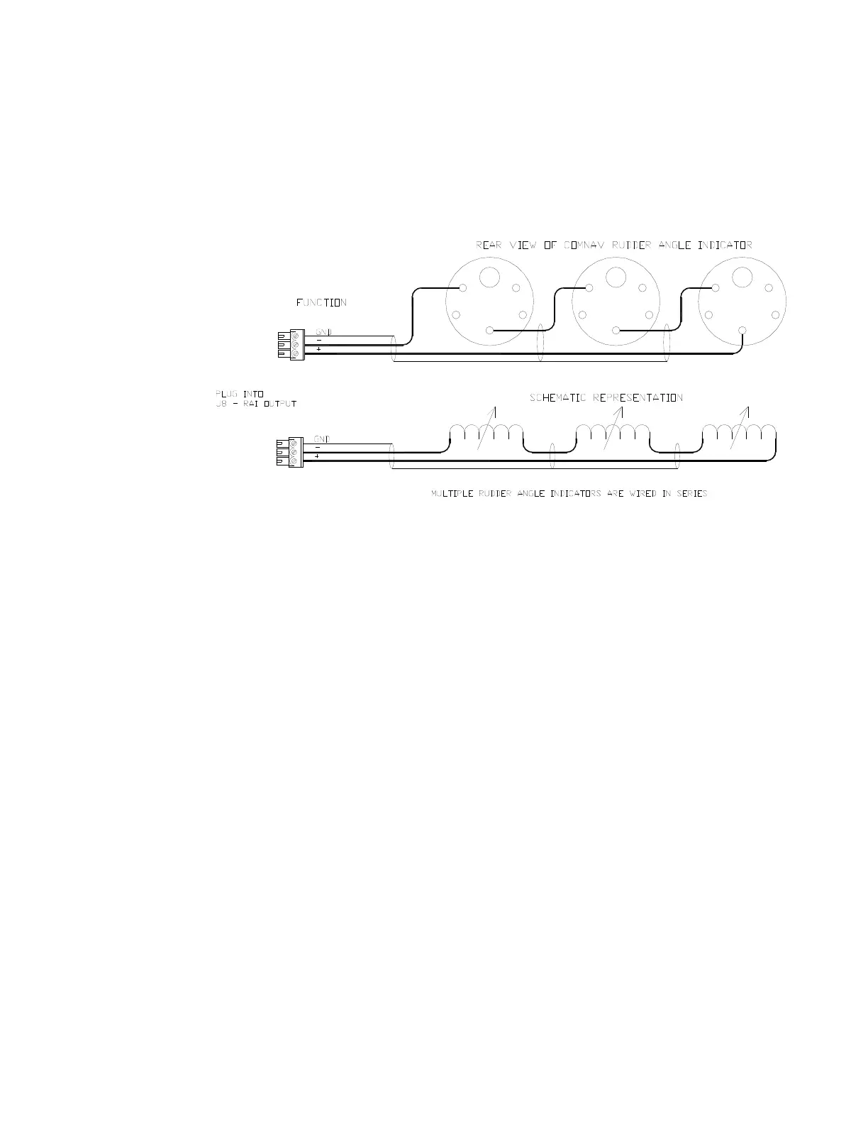
The P4 system will drive up to five 500 microampere Rudder Angle Indicator (RAI) meters, such
as those supplied by ComNav (PN 20360014). Mounting instructions are included with each
meter. Wire the meter to the plug for the SPU receptacle labelled J8 – RAI OUTPUT. If you have
more than one RAI meter, they should all be wired in series, as shown in Figure 32:
Figure 32 – Wiring Connections for Rudder Angle Indicators
Drive Outputs
The P4’s SPU is capable of directly driving a variety of steering systems. Optional Drive Boxes
are available for those systems not handled directly by the P4. Contact your ComNav Dealer for
more information.
Reversing Direct Current (DC) Motor Hydraulic Systems
The P4 SPU can directly handle reversing DC motor hydraulic pumps drawing up to
approximately 20 amps. For larger current requirements, the ComNav CT2 Drive Box should be
used. To connect the pump motor directly to the SPU, use the diagram in Figure 33. Note that
wire polarity is not important, since the P4 will automatically make the necessary adjustments
internally when the system is set up.
Note: Two very important steps when installing any hydraulic system are to bleed it of any air
trapped in the fluid, and to check for fluid leaks.
Installation