ComNav P4 Installation and Operation
Document PN 29010100 V1r0 - 68 -
NOTE: An NMEA 0183 serial data stream is inverted by the transmitter, and inverted
again by the receiver, and so a logical “1” in the data appears as a logical “0” on the A/B
wire pair. The “ground reference” voltage for the output signals is available on the GD pin
of J6 – but note that this is not the
SPU’s Signal Ground, rather it is a synthesized
reference voltage, and so it must not be connected to any other ground.
Typical RS-422 Signals
The only way to troubleshoot problems with the RS-422 NMEA signals to-and-from the P4 is
with an oscilloscope, due to the fact that a multimeter is essentially useless for
differential
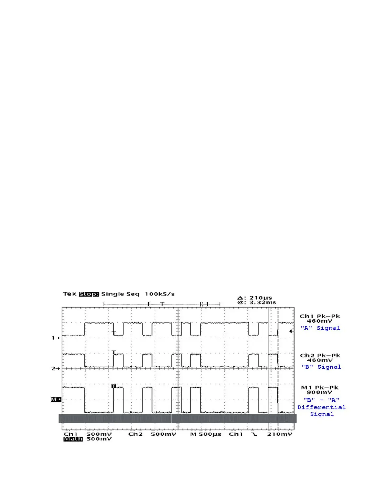
signals. Figure 45 shows an example of a typical NMEA 0183 RS-422
transmission,
captured on a dual-trace oscilloscope.
The data stream is from a P4 SPU’s NAV - OUT port. Channel 1 is the RS-422 “A” signal,
Channel 2 is the “B” signal, and the math trace is the differential voltage between “A” and “B.”
The oscilloscope probes were manually set at 10x, so the voltages of the signals are 10 times
larger
than measured below. The Ground Reference for the oscilloscope’s inputs was the GD
pin of the
J6 – NAV I/O connector. The Baud Rate was 4800 (or ~208.3 msec per bit).
The data being sent is the first two characters at the start of the NMEA sentence: $A (the full
sentence might have been $APHDM,346.5,M*37 or something similar).
In hexadecimal, $A is: 0x24, 0x41; in binary: 0b00100100, 0b01000001. Following the rules
of NMEA 0183, that binary data was transmitted starting with the least
significant bit of the
first character, in 8-bit groups: 00100100, then 10000010 (as shown in
the blue overlay in the
figure below). The transmitter circuit demarked each group (“byte”) by
a leading `0´ Start bit
and a trailing `1´ Stop bit. Finally, the train of bits was sent to the RS-422 differential driver
output circuit, which put inverted bits on the `A’ signal line, and
non-inverted bits on the `B´
line. Before transmission from the RS-422 driver started, the signals were in the Idle state:
`A´ was
at a low voltage with respect to `B´ (the same state as a `1´ bit). After all the bits of
the full
sentence had been transmitted, the signals would have returned to the Idle state.
Figure 45 - A typical NMEA 0183 RS-422
transmission
Installation