ComNav P4 Installation and Operation
Document PN 29010100 V1r0 - 48 -
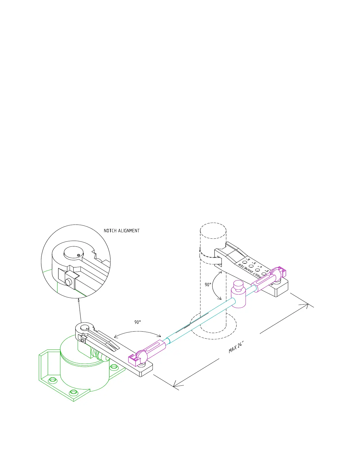
Rotary Rudder Follower
Mounting
Install the Rudder Post Arm on the rudder post using a stainless steel band clamp (not
supplied). Bolt the ball joint to the hole in the Rudder Post Arm corresponding to the diameter of
the Rudder Post in inches, making sure the ball is facing upwards.
Mount the Rudder Follower so that the Rudder Follower Arm is the same height as the Rudder
Post Arm. The Rudder Follower is centered when the arm is directly above the cable gland (see
Figure 21).
The distance between the centerline of the Rudder Post and the Rudder Follower must not
exceed 24 inches. Make sure that the ball joints on the Rudder Arm and Rudder Follower arm
are facing upwards as shown.
Snap the rod assembly onto the ball joints. Be sure to close the release clamps on each socket,
and then adjust the length of the rod to get the correct geometry with the rudder dead-ahead.
If the locking screw in the Rudder Follower arm has been loosened, or the arm removed from
the Rudder Follower, re-attach the arm and check the potentiometer center position.
When the rudder is dead-ahead, the electrical resistance between the wires of the black and
green wire pair, and the wires of the white and green wire pair, should be equal (approx. 600
ohms each).
Be careful to check the installation for any mechanical obstructions or binding of the linkage,
and correct it now, before it becomes a problem.
Figure 21 – Rudder Follower Linkage Geometry
Installation