ComNav P4 Installation and Operation
Document PN 29010100 V1r0 - 64 -
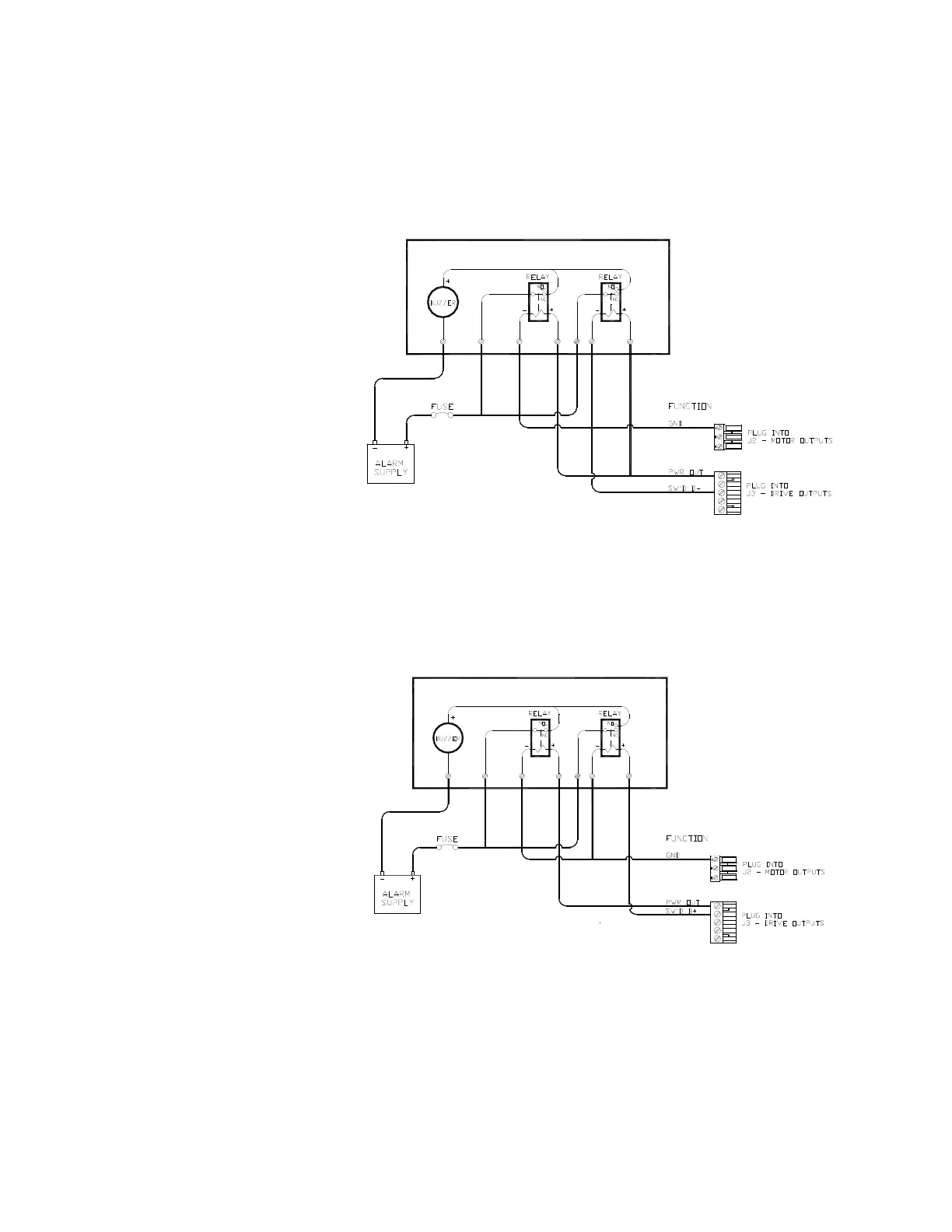
Power Failures
Some installations require separate monitoring for power failures. This can be accomplished with
the circuit in Figure 42, which utilizes two relays. The coil voltage of the relays should match the
supply voltage for the autopilot. The power for the Alarm Supply, which must be a separate,
dedicated supply from the autopilot supply, should match the voltage of the alarm.
Figure 42 – External Alarm, SW'D B- Output – with Power Fail Option
The alternative circuit, using Switched B+ (SW'D B+) as the alarm output:
Figure 43 – External Alarm, SW'D B+ Output – with Power Fail Option
I
nstallation