MAINTENANCE Removing the controller
Cubiscan 325 62
5. Locate the controller (the black box located below the gate’s home
position).
Remove the nut using an 11/32'' nut driver (see Figure 57).
6. Disconnect all connectors that are attached to the controller box (refer
to Figure 58 as needed), as follows:
• To remove the Ethernet cable connector, press the tab on the
connector to release it, and pull it straight out.
• To remove the USB and display cable, simply pull it straight out using
even pressure.
• To remove the serial and load cell cables, loosen the screws and pull
the cable connectors out using even pressure.
• To remove the gate DB9 connector and the gate DB25 connector,
use a Phillips head screwdriver to loosen the screws, and pull the
cables straight out.
• To remove the gate power, proximity sensor, and encoder cables;
unscrew the cables and pull them straight out.
• Remove the nut holding the ground cables in place and detach the
ground cables from the controller.
7. Verify that all cables have been removed from the controller, then lift
the box up and pull it out sideways (to the right) until it is clear of the
metal frame of the Cubiscan 325.
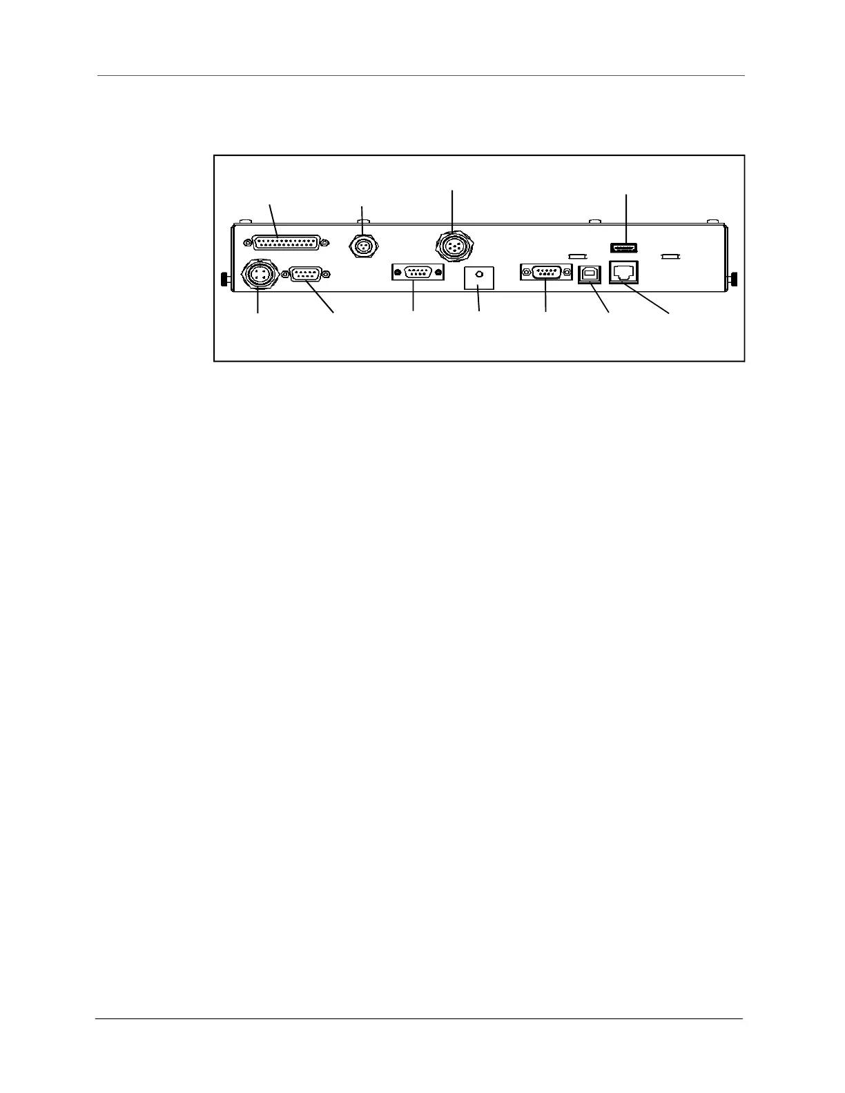
Figure 58
Drawing of controller
Gate DB25
Gate
Power
Gate
DB9
Proximity
Sensor
Encoder
Load Cell
Serial
USB
Ethernet
Display
Ground
Cables