8 Culligan® Smart Controller (GBE) for Softeners and Filters
8 Cat. No. 01021161
Cable Routing
All input and output connections to the circuit board are 24 Volt or less.
Although the cables do not have to be run in conduit, it is necessary that long runs of cable be supported or protected by
strapping them to the equipment piping. If conduit will be used to route the shielded cables, three factors must be consid-
ered:
1. DO NOT share the same conduit or raceway with 120 Volt or higher circuits.
2. Keep cables at least six (6) inches away from 120 Volt or higher electrical circuits.
3. GROUND the conduit (if metallic) to a known “earth ground” location.
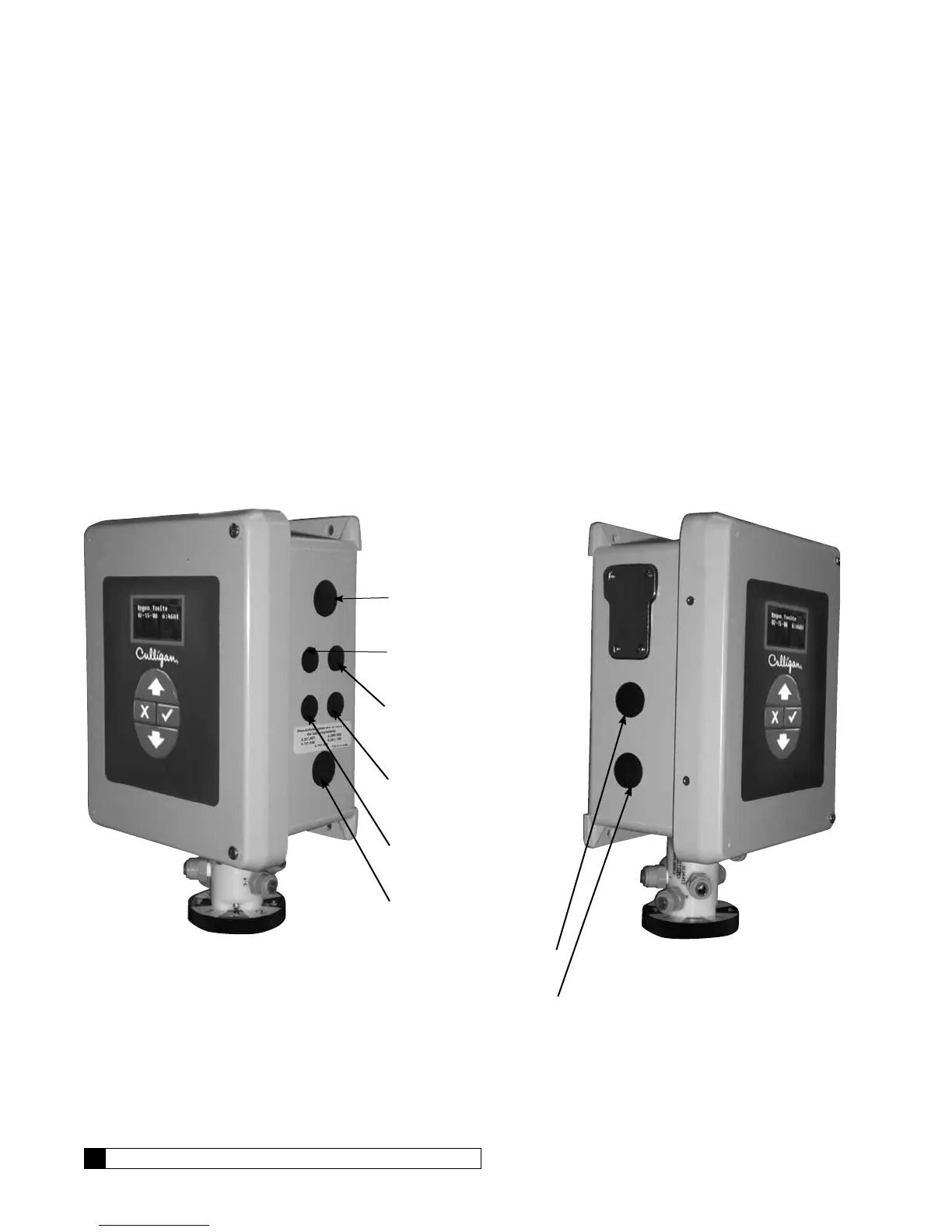
A series of holes are located on the sides of the Smart Controller (see Figures 6 and 7). Strain relief fittings are provided
with the controller enclosure for interconnecting wiring. Install the plastic fittings as needed. Remove the compression nut
and rubber sleeve from each fitting. Prior to connection of the cable wires to the circuit board, slide the compression nut
and sleeve over the cable for the wiring connections. When wiring is completed, apply a small amount of silicone to the
rubber sleeve and reassemble. This will assure all wiring is secure and assist in making the tightening of the fitting easier.
Insert the plugs provided to block any holes not used for wiring or other accessories.
Right Side View
Brine Reclaim Solenoid
(optional)
Input Connection
for Flow Sensor
Output Connection
for Remote
Accessories
Input Connection
for Remote
Accessories
24 Volt Power
Input Connection
Brine Reclaim Solenoid
(optional)
Figure 6.
Brine Refill Valve
Blocking Solenoid for
Alternating Operation
Left Side View
Figure 7.