Installing Accessories 63
Cat. No. 01021161
Smart Controller Alarm Signal Output
The Smart Controller Alarm Signal Output is provided thru three screw terminals located on the Plug-in Circuit board.
These terminals provide a pair of dry contacts rated at 10 A at 240 VAC. One dry contact is open and one is closed at all
times as defined in the table below.
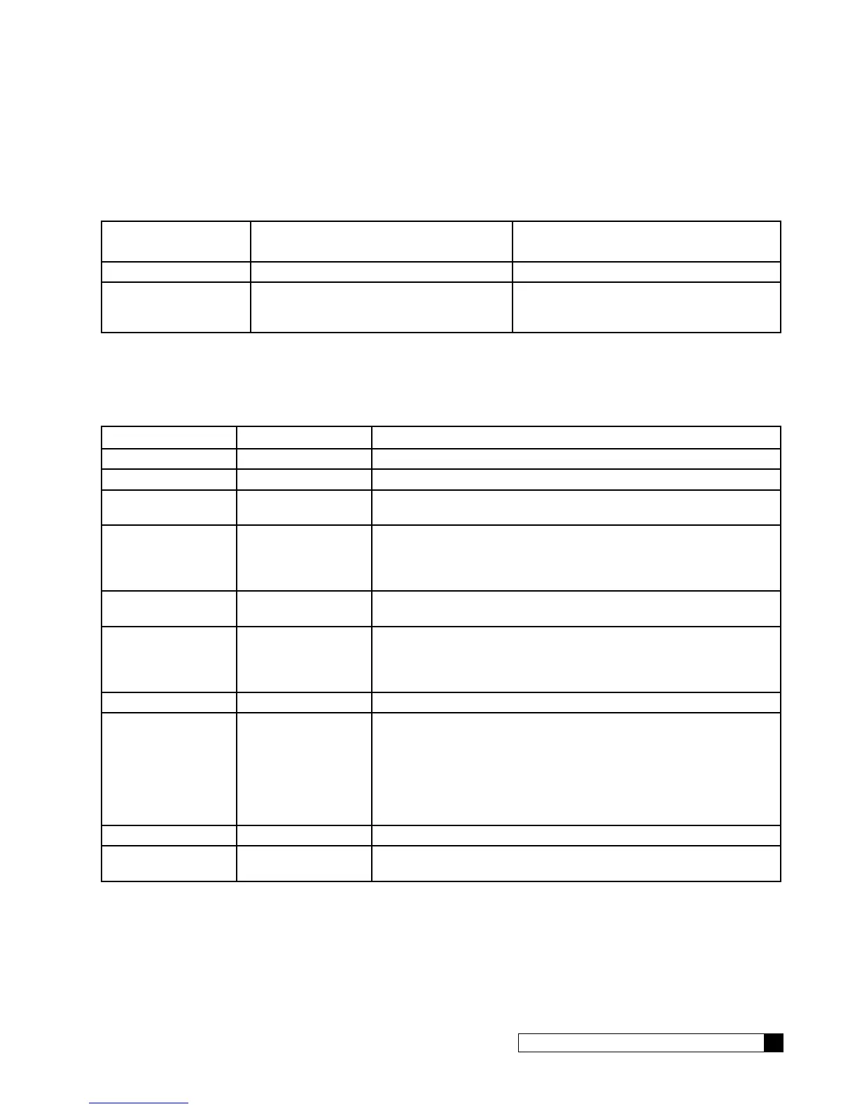
When Smart
Controller is…
Contact A (screw terminals 1 & 2) Contact B (screw terminals 1 & 3)
Operating Normally Continuity Open circuit
In “Error Condition”, or
when the Smart Control-
ler is not powered on
Open circuit Continuity
A simple error alarm can be constructed by routing a customer supplied power source thru the Alarm Signal Output
contact terminals 1 & 3 as shown in figure 44. The indicating light will be ON any time that the Smart Controller is either
not powered on, or if it is in an “error condition.” Alternatively, the Alarm Signal Output contact terminals can be wired to
a customer supplied PLC or SCADA system to provide an indication to the customer of the status of the Smart Controller
equipment.
Error Add Sensors Meaning
Motor Pos Err No Control valve drive motor or motor position sensors have failed
Motor Home Err No Control valve drive motor or motor position sensors have failed
GBE is unpowered
(or board has failed)
No
Ext Filter Alarm No Smart Controller has a programmable count-down gallonage alarm.
This error indicates that the countdown has reached zero. Typically
this alarm is used as a reminder to replace filter media in an external
canister filter
Aqua Salt Error Aqua-Sensor The most recent regeneration was unsuccessful because the strength
of the brine was too low.
Low Salt Level SBT Probe This alarm is a prediction that the solid salt remaining in the brine tank
will need to be replenished within the next 14 or fewer days. (The
predicted days-salt-remaining an be viewed on the Smart Controller
display screen.)
Brine Overfill SBT Probe There is too much water in the brine tank.
Brine Blocked SBT Probe The rate of brine draw during the most recent eduction was too slow.
The eduction system is either partially clogged or a vacuum leak has
formed in the eduction system.
-or-
There was not enough water in the brine tank at the end of fill (which
could also be due to a blocked brine line)
Salt Bridging SBT Probe There appears to be a salt bridge in the brine tank
No RF Remote Signal RF wireless remote The controller has lost RF communication with the Smart Controller
wireless remote.
Table 2. Error Conditions on the Smart Controller which will trigger the Alarm Signal Output.
On a multiple-tank softener system, such as a twin-alternating, or progressive flow network, the Alarm Signal Output Re-
lay board must be installed on each Smart Controller that the user wants monitored for errors.
When the Smart Controller senses any of the error conditions listed in the table above, the alarm output signal will be
triggered. In order to determine the actual individual error(s) which triggered the alarm output signal to be triggered, you
would either need to refer to the Smart Controller display screen itself, or to use the PLC communication process de-
scribed in this installation manual.