40 Culligan® Smart Controller (GBE) for Softeners and Filters
40 Cat. No. 01021161
Progressive Flow or Parallel Flow
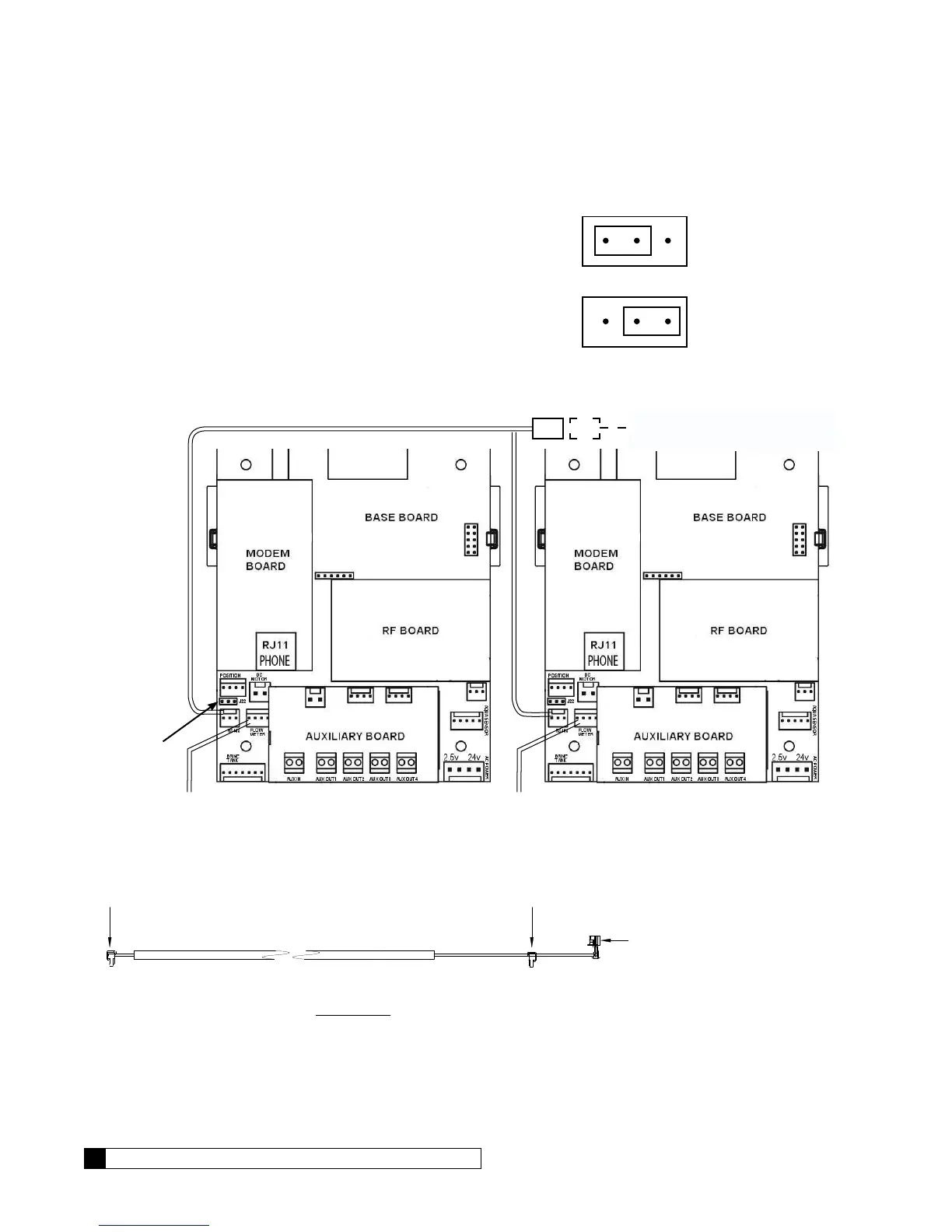
IMPORTANT—Setting the Jumpers for Progressive Flow
For progressive flow to operate properly, the first and last units must have
the jumpers set to pins 1 and 2 on terminal J22 (see Figure 25 at right).
All middle units should have the jumpers on pins 2 and 3 (see Figure 25).
The diagram below (Figure 26) shows duplex connections. Repeat the
connections on any additional systems.
To Additional Units
(if necessary)
Communication Cable 01016327
Jumper
Location
Flow Meter Flow Meter
Unit 1 Unit 2
Figure 26. Duplex connections.
To RS 485 Comm Port
on GBE Circuit Board, #1
CABLE 01016327
To RS 485 Comm Port
on GBE Circuit Board, #2
PARALLEL
Additional communication cable
connections are used when there
are three or more controls. Connect
end of second-(01016327) cable
to this connector and other end of
cable to RS 485 Comm Port on third
GBE Circuit Board.
Figure 27. Parallel cable for Smart Controller.
Jumper location for
first and last units
(end units).
Jumper location for
middle units.
1 2 3
Figure 25.