46 Culligan® Smart Controller (GBE) for Softeners and Filters
46 Cat. No. 01021161
Sequence of Operation
When a softener is in standby or a regeneration cycle, the Smart Controller sends a signal to the P7 Sol-Vlv terminal of
the primary circuit board, activating the solenoid valve. The orange LED will be on at this time. When the solenoid valve
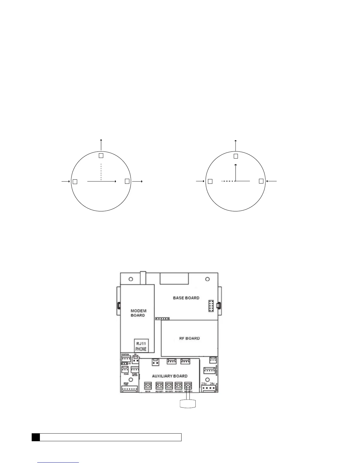
is electrically activated, ports #1 and #2 of the solenoid (Figure 32) become common. This will direct pressure from a con-
stant IN pressure supply to the blocking diaphragm valve, which prohibits the flow of water to service.
Once the Smart Controller signals the unit to return to a Service status, the signal from P7 Sol-Vlv is removed and the
solenoid valve is deactivated. When the solenoid valve is electrically deactivated, ports #1 and #3 of the solenoid become
common. The orange LED will not be on at this time. This will vent pressure, from the diaphragm valve to drain. The dia-
phragm valve opens to allow softened water to flow to service.
3
2
1
To Drain
Blocking
Diaphragm
Solenoid Valve Energized
When Tank
in Regen or Standby
N/C
N/O
N/O
2
3
1
To Drain
From
Pressurized
Source
From Blocking
Diaphragm Valve
Solenoid Valve Not Energized
When Tank "Online"
Solenoid Valve
N/C
N/O
N/O
Solenoid Valve
From
Pressurized
Source
Figure 32.
S O L
Figure 33. Smart Controller board with solenoid connection.