Appendix B Data Port Output 93
Cat. No. 01021161
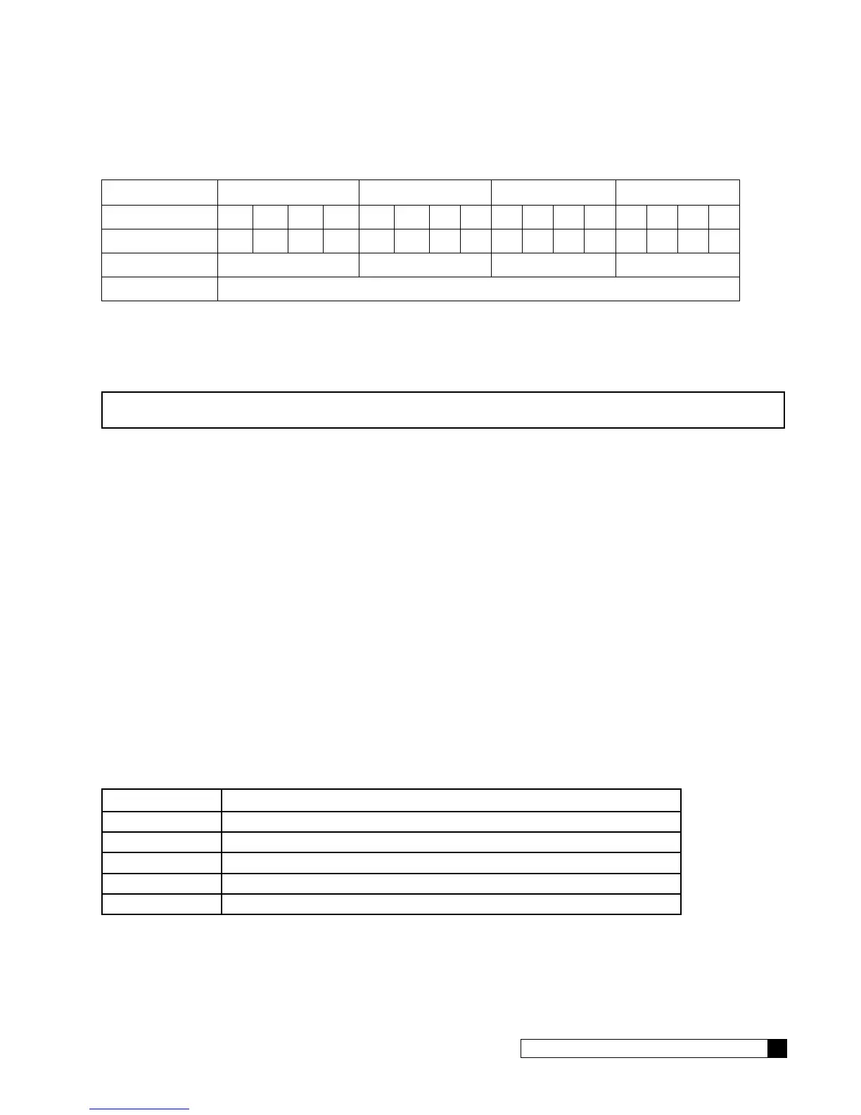
If there were a ‘Replace Media Filter’, ‘Aquasensor Salt Err’ and ‘Motor Position Sensor Error’ present then bits 4, 6 and 8
would be set to 1 and all other bits would be 0, respectively.
W X Y Z
Error Bits 15 14 13 12 11 10 9 8 7 6 5 4 3 2 1 0
Binary 0 0 0 0 0 0 0 1 0 1 0 1 0 0 0 0
hexadecimal 0 1 5** 0
Error Flag 0x0150
*Note that the first two characters of the error flag are always “0x” to signify that this is a hexadecimal number
** In hexadecimal, the number 4 bit equals 1, the number 5 bit equals 2, the number 6 bit equals 4, and the number 7 bit
equals 8. Therefore, when you add the #4 bit value to the #1 bit value, you get 5.
So the value of the error flag would be 0x0150 if these three errors were present.
NOTE If the GBE is controlling a filter (instead of a water softener) then the above message definitions are
identical, but that error flags 1,2,3,6,9 and 11 will always be zero for a filter.
Progressive Flow System of Smart Controller-Controlled Water Softeners
The format of the status message for a progressive flow network consists of a series of individual lines of information, one
line for each of the Smart Controller-controlled softeners. For example, in a triplex progressive flow network, every 60
seconds, the data port on the master unit will send out the following three lines of information:
CULL,A1,B1,C1,D1,E1,1,G1
CULL,A2,B2,C2,D2,E2,2,G2
CULL,A3,B3,C3,D3,E3,3,G3
example:
CULL,00052754,000003.7,1,00009110,0x0000,1,0329101314
CULL,00042674,000003.5,1,00004321,0x0000,2,0329101314
CULL,00010204,000000.0,4,00005444,0x0000,3,0329101314
The 1 at the end of the first line indicates that this line is the status for the Master unit in the progressive flow network.
The 2 and 3 on the subsequent lines indicate that this data is for slave unit #1 and slave unit #2, respectively. The infor-
mation contained on each line is of the same format as described in the Single softener section above.
Electrical Connections
The Culligan Data Cable Connector is terminated with a D-sub9 style female termination. The customer must provide the
following pin connections:
Pin Function
3 (Input) TD (data coming FROM the GBE board
2 (Output) RD (this line is required even though no data is sent TO the GBE board)
7 (Input) RTS
8 (Output) CTS
5 (Signal gnd) GND
The data coming from the Smart Controller board is at the following conditions:
Bits Per Second: 9600
Data Bits: 8
Parity: None
Stop Bits: 1
Flow Control: None