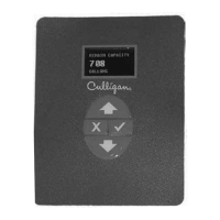
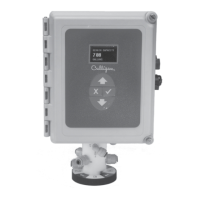
62 Culligan® Smart Controller (GBE) for Softeners and Filters
62 Cat. No. 01021161
Alarm Relay Board/Chlorinator Settings
Setting Screen Display Range Changing the Setting
Chlorina-
tor
Chlorinator
Error
Status
Network
Normally
On
Normally
Off
Repeat
Cycle
Chlorinator—Used to control a chlorinator. Not used in commercial/in-
dustrial applications.
Error Status—This mode of operation occurs when the relay board is
plugged into the GBE board chlorinator socket. When Error Status is
selected, this relay is in the Normally Open position when the GBE
board has power AND there are no errors present (“Problem Found” is
not showing on the Home screen). The relay is in the Normally Closed
Position when the GBE is either powered OFF or when there is an er-
ror present on the GBE board.
Network – currently not used.
Normally On—Sets up relay to be Aux5. For this option, select cycle,
delay time and duration. In this mode, the relay is energized through
all cycles EXCEPT the cycle you designate. Further, it will delay de-
energizing the relay for the duration designated. It will de-energize
during that cycle for the amount of time you set after the delay.
Normally Off— Sets up relay to be Aux5. For this option, select cycle,
delay time, and duration. In this mode, the relay is NOT energized
through all cycles EXCEPT the cycle you designate. Further, it will
delay energizing the relay for the duration designated. It will be en-
ergized during the selected cycle for the amount of time you set after
the delay.
Repeat Cycle— Sets up relay to be Aux5. For this option, select cycle,
delay time, “on” time, and “off” time. Once the relay energizes in the
selected cycle, it will repeat the “on” time and “off” time settings until
the cycle ends.
Chlorina-
tor
Installed,
Not
Installed
Press
or and then to select INSTALLED if a Chlorina-
tor board is installed inside the Smart Controller.
Power
Level
Low
Medium
High
Press
or and then to change the Chlorinator power
level setting. Change this setting only if a Chlorinator is installed.
On Time
1–20
Press
or and then to specify the number of minutes the
chlorinator will operate during the brine draw phase.
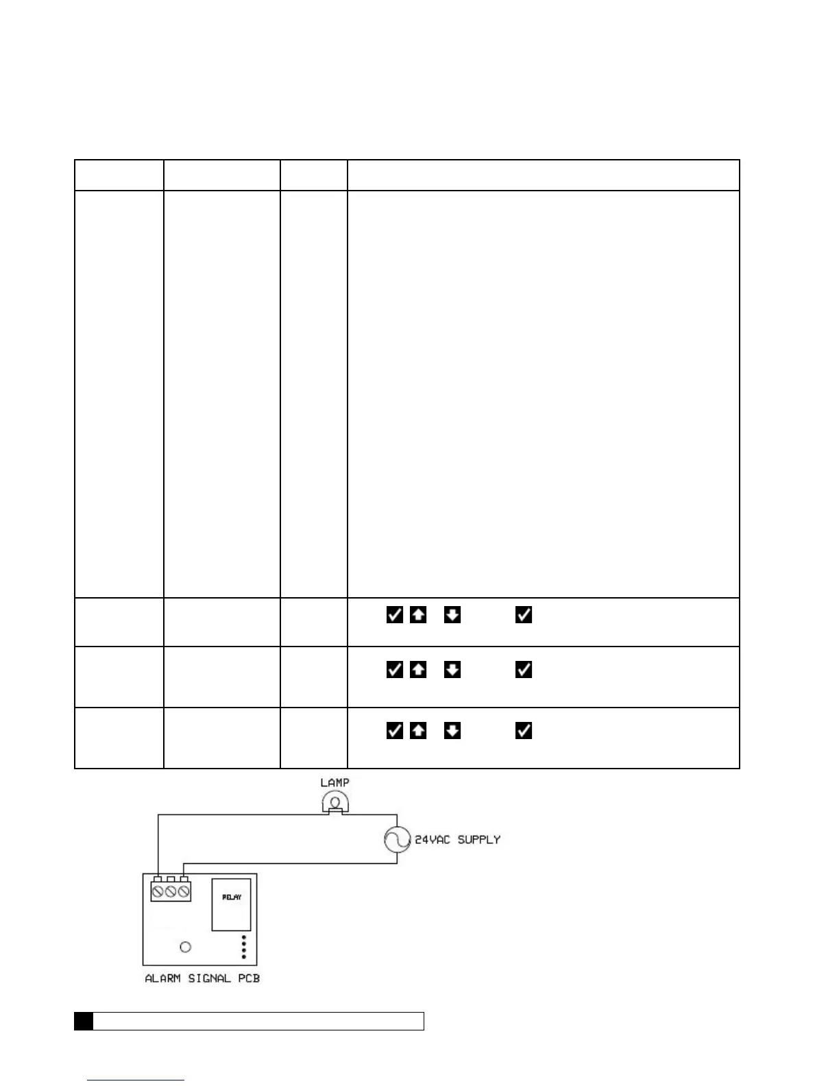
NORMAL OPERATION:
Terminals 1 and 2 are connected, leaving the lamp circuit open (lamp off)
ERROR CONDITION:
Terminals 1 and 3 are connected, completing the lamp circuit (lamp on)
1-COM
2-HC
3-HD
Figure 44. Example of customer wiring to the GBE Alarm Signal Output