Installing Accessories 57
Cat. No. 01021161
Installing the Wireless Remote
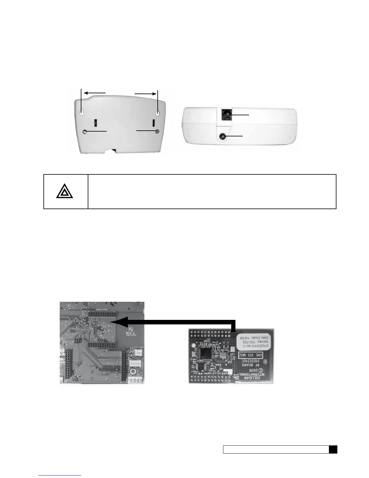
1. Select a location for the wireless remote monitor (Figure 40). The location must be near an electrical outlet. If a
modem is used in the remote, then the location should also be near a standard RJ-11 type telephone wall jack.
MODEM CONNECTION
POWER CONNECTION
SCREWS
5 3/8”
Figure 40. Wireless remote monitor.
CAUTION! Do not touch any surfaces of the circuit board. Electrical static discharges may
cause damage to the board. Handle the circuit board by holding only the edges
of the circuit board. Keep replacement boards in their special anti-static bags
until ready for use. Mishandling of the circuit board will void the warranty.
2. Use the Hole Drilling Template as a guide to drilling two holes to mount the remote monitor. If drilling into wall
board, drill two 5/16” diameter holes and insert the plastic drywall anchors into the holes securing them with the
two #10 screws provided. If drilling into a solid surface, drill two 7/32” holes into the surface and screw the two
#10 screws into the holes. In either case, leave a gap of approximately 3/32” between the head of the screw
and the wall.
3. (Optional) If a modem is to be installed into the remote monitor, refer to page 53 for installation and setup.
4. Connect the power cord to the bottom of the remote monitor. If a modem is to be used in the remote, plug a
standard telephone extension cord into the bottom of the remote monitor.
5. Hang the remote monitor on the two screws.
6. Disconnect power to the softener. Open the control and connect the RF board into the controller circuit board.
Make sure the RF board is fully seated into all of the sockets (see Figure 41). Reconnect power.
Back of GBE Board RF Board (note orientation)
Figure 41. RF board location on Smart Controller board.
7. Install RF board into unit controller. Line up pins in RF board and press firmly into black connectors. Note orien-
tation of RF board (see Figure 41).
8. Follow the directions on the next page to program BOTH the main and remote monitor units to communicate
with each other. If modem has been installed in the remote, it is also necessary to follow the directions in the
next section of this manual to configure the main controller to use the modem in the remote.