Smart Controller Circuit Board Layout 11
Cat. No. 01021161
Smart Controller Circuit Board Outputs
The circuit board supports four outputs:
• Motor control (DC Motor)
• Blocking valve (Use Aux Out 4)
• Two programmable auxiliary outputs (Aux Out 2 and Aux Out 3) for commercial four-cycle and five-cycle valves.
• Controller interface (communication between multiple controllers) (RS485).
CAUTION! Connecting 24 V to the 2.5 V connection on the circuit board will damage the circuit
board.
NOTE If you are using Aqua-Sensor
®
, you should run the 2.5 V wiring now as the cable is run through the
same cord grip. See page 12 for details.
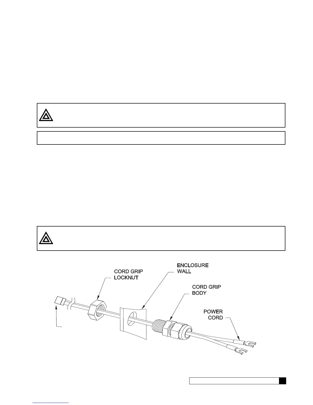
Wiring the Smart Controller Power Cord
1. Locate the power cord among the controller parts. It has a white connector on one end and two spade connec-
tors on the other.
2. Locate the cord grip among the parts.
3. To assemble the power cord, first run the cord grip nut over the spade terminal end of the power cord.
4. Next, run the spade terminals through a hole in the side of the controller FROM THE INSIDE (see Figure 12).
5. Finally, run the cable through the bottom end of the cord grip, and assemble the grip to the controller wall.
6. Plug the board connector to the board where it is labeled 24 V. The connector has four (4) connections but only
two wires are connected. The other end of the power cord (with spade terminals) should be connected to the
two 24 VAC terminals on the transformer (see Figure 13).
CAUTION! DO NOT PLUG THE TRANSFORMER INTO THE WALL UNTIL ALL WIRING IS
COMPLETED.
7. Repeat the process for any additional units in the system.
METAL TABS
Connect to white connector
on main power cord
If using Aqua-Sensor,
plug metal tabs at end
of cord into connector
Figure 12. 24 V Power Connection