Installation 9
Cat. No. 01021161
Smart Controller Overview
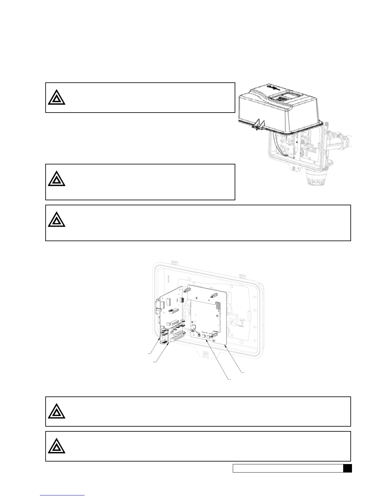
To access the inside of the Smart Controller, refer to the instructions below.
CAUTION! Failure to complete the following steps might
result in damage to the keypad or circuit
board!
1. Loosen the front cover screw.
2. Hinge the front cover upwards. (See Figure 8). Do not remove the
front cover yet.
3. Disconnect the keypad from the circuit board.
4. Remove the front cover.
CAUTION! Grip all connections to the circuit board by
connecting terminals for assembly and disas-
sembly. Failure to do so could result in dam-
age to the wire leads or connecting terminals.
CAUTION! Do not touch any surfaces of the circuit board. Electrical static discharges may cause
damage to the board. Handle the Smart Controller circuit board by holding only the
edges of the circuit board. Keep replacement boards in their special anti-static bags
until ready for use. Mishandling the circuit board will void the warranty.
5. The circuit board is held on with plastic posts. Push the locking clip at the end of the posts to allow the circuit
board to be removed from the daughter board.
GBE CIRCUIT BOARD
AUXILIARY CIRCUIT BOARD
CIRCUIT BOARD BRACKET
INTERFACE CIRCUIT BOARD
Figure 9. Locking clip.
CAUTION! Properly connect the wire connectors to the circuit board. The wires must exit the plug-
in connector opposite of the raised white base of the circuit board connector.
CAUTION! Take extra care when connecting the 2.5 VAC and 24 VAC power. Failure to connect
properly will result in damage to the circuit board.
Figure 8. Circuit board.