WARNING (HP, IN)
The information in the remainder of this section can be used to design Specialty Input Devices compatible with the Omni2.
The input device manufacturer must ensure that the SID design is safe under all conditions, in particular, single component
failures must be detected and the input device put into a safe condition. Curtiss-Wright accept no responsibility for losses
of any kind resulting from an unsuitable SID design.
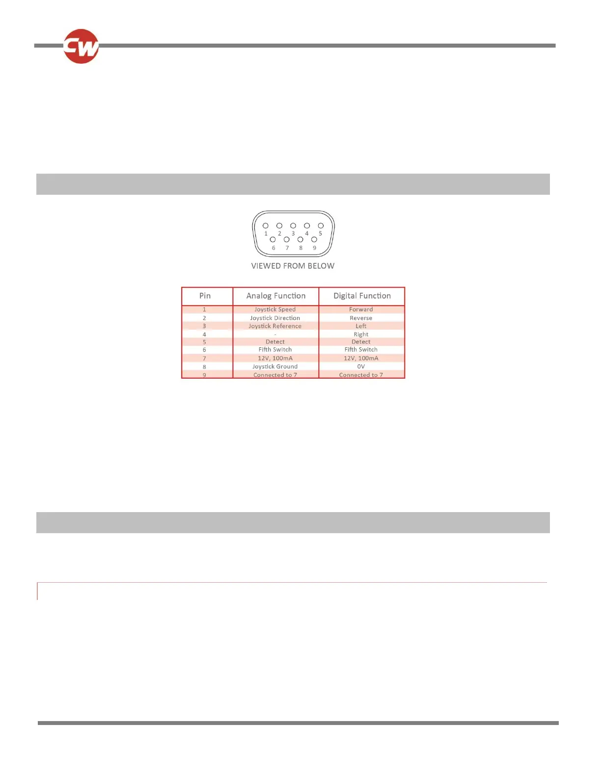
3 9-WAY D-TYPE PIN-OUT
The pins of the 9-way D-type connectors will have a different function depending on whether the Omni2 is configured for an
analogue or a digital-type input device.
WARNING (HP, IN)
The mating 9-way D-type connector (socket) should always be fitted with gold contacts and a suitable backshell with
locking screws. These locking screws should be used to mechanically hold the connector firmly in place.
4 ANALOGUE SIGNAL LEVELS
The analogue inputs are compatible with PG Drives Technology JC200BR3K1Y and Flightlink I5X1SSG251020 joysticks.
4.1 PIN 1 – JOYSTICK SPEED
This is the joystick signal that determines the forward/reverse component of powerchair movement. The joystick has a 1.8K
resistor in series with the speed output as shown below. All voltage levels apply to the actual joystick output, i.e. no load
values. The Omni2 has an input resistance of 100K to 0V.
 Loading...