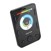
8.1 JOYSTICK AND USER SWITCH
Typical applications are chin control, foot control or heavy/light operating-force joysticks.
The joystick must be compatible with the electrical specifications shown in the Specifications chapter. A typical example
would be a PG Drives Technology joystick e.g. D50064, connected to the Omni2 via the 9-way D-type connector. In addition, a
User Switch is required and connects to the Omni2 via the 3.5mm / 1/8” jack socket.
8.1.1 JOYSTICK CALIBRATION
If a new Joystick-Type SID is fitted, then the following calibration procedure must be performed. If it is not, the powerchair
may not drive in a straight line or reach maximum speed.
To begin the procedure you must first enter OBP Mode and go to the System branch. Select the Joystick Calibration option.
The procedure is automatic, simply follow the on-screen instructions. Values for both the forward/reverse and left/right SID
axes will be displayed. Alongside each value will be a X or a symbol.
X – Indicates the axis value is outside of the permitted calibration range for the particular SID direction.
– Indicates the axis value is within the permitted calibration value for the particular SID direction.
Simply deflect the SID in the instructed direction until both values are within the permitted ranges. Repeat for all four
directions.
A large tick will be displayed on screen, for a short period of time, when the calibration has been completed successfully. The
screen will then return to the System Menu.
8.2 FIVE SWITCH AND USER SWITCH
Typical applications are Tash Penta switches, Buddy Buttons, or products from ASL and Switch-It.
The device comprises of 4 direction switches and one User Switch, connected to the Omni2 via the 9-way D-type connector. In
addition, a normally-closed User Switch should be connected to the Omni2 via the 3.5mm / 1/8” jack socket. This switch,
although functionally identical to the Fifth Switch input on the 9-way D-type connector, is required to provide a fail-safe
emergency-stop system.

 Loading...