User's Manual
36
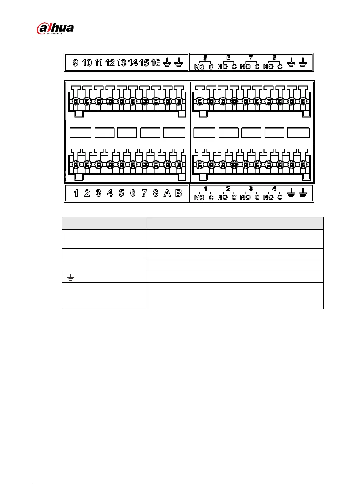
Figure 3-12 16/24-HDD series (2)
Table 3-2 Alarm port
Icon Description
1–16
They are corresponding to ALARM 1–ALARM 16. The alarm
becomes valid in low level.
NO1 C1–NO8 C8 Eight groups of normally open linkage output (on-off value).
+12V Constant power output, 500 mA current.
Grounding wire.
A, B
A and B: Control the A/B cable of the RS–485 device. It is used to
connect to the PTZ camera. Please parallel connect 120 Ω
between A/B cables if there are too many PTZ decoders.
3.4.1.3 Alarm Input
Both NO and NC are supported. For connection of NC alarm input port, see the following figures.
●
GND and COM of alarm device shall be connected in parallel. Alarm device shall be powered with
external power source.
●
Connect GND of alarm device with GND of Device in parallel.
●
Connect the NC port of alarm device to the alarm input port (1–16).
 Loading...