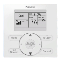
5.4 HRV <BRC301B61> 89
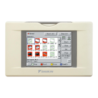
Remote Controllers
Setting of remote controller for HRV unit
List of Settings
Note:
1. indicates the setting position at the factory.
2. The settings are applied to the entire group, but if the mode no. inside the parentheses is selected, the settings can be applied to
individual indoor units.
However, it is only possible to check any changes made to the settings inside the parentheses in individual mode.
(For group batch operation, the changes are made but the display remains as it was when shipped from the factory.)
3. Do not set anything not shown above. If the applicable functions are not available, they will not be displayed.
4. When returning to normal mode, the remote controller is initialized, so the display might show “88.”
5. Group number setting for centralized controller
(1) Mode No. 00 : Group controller
(2) Mode No. 30 : Individual controller
* Regarding the setting procedure, refer to the section “Group number setting for centralized control” in the operating manual
of either the on/off controller or the central controller.
6. Details of external input setting
“Last command”.............Only when HRV units are in independent operation. External input is not available with interlocked operation
of HRV units and air conditioners.
“
Priority on external input
” .......Remote controllers are available while the external input terminal is closed. Remote controllers are not
available while the external input terminal is open. External input is not available with interlocked operation
of HRV units and air conditioners.
“
Priority on operation
” .......Either air conditioner remote controllers with interlocked operation of HRV units and air conditioners, or
external input is in operation, when HRV units are in operation.
Setting is available with interlocked operation of HRV units and air conditioners.
7. Details of external input terminal function are as follows:
* Setting position “04” does not function with interlocked operation of HRVs and air conditioners.
C : 3P034928-5J
Mode No.
Setting
switch
No.
Description of Setting
Setting position No. (NOTE 1)
Group
settings
Individual
settings
01 02 03 04 05 06
17 27
0 Filter cleaning time setting
Approx.
2500 hours
Approx.
1250 hours
No counting – – –
1
Nighttime free cooling operation start time
(after other air conditioners operating
together with the unit have been stopped)
Off 2 hours 4 hours 6 hours 8 hours –
2 Pre-cool/pre-heat on/off setting
OffOn––––
3 Pre-cool/pre-heat time setting
30 min 45 min 60 min – – –
4 Fan speed initial setting
Normal Ultra high – – – –
5
Yes/No setting for direct duct
connection with VRV system
No duct
(Air flow setting)
With duct
(fan off)
––––
Setting for cold areas (Fan operation
selection for heater thermo OFF)
––
No duct With duct
Fan off Fan L Fan off Fan L
6
Nighttime free cooling operation air
flow setting
High
Ultra high – – – –
7 Centralized/individual setting
Centralized
Individual – – – –
8 Centralized zone interlock setting
NoYes––––
9 Pre-heat time extension setting
0 min 30 min 60 min 90 min – –
18 28
0 External signal JC/J2
Last
command
Priority on
external input
Priority on
operation
–––
1 Setting for direct Power ON
OffOn––––
2 Auto restart setting
OffOn––––
3 External damper operation
––On–––
4
Indication of ventilation mode/Not indication
Indication
No Indication
––––
7 Fresh up air supply/exhaust setting
No Indication No Indication
Indication Indication – –
Supply Exhaust Supply Exhaust – –
8
External input terminal function
selection (between J1 and JC)
Fresh-up
Overall
alarm
Overall
malfunction
Forced off
Fan forced
off
Air flow
increase
9
KRP50-2 output switching selection
(between 1 and 3)
Humidifying
on/off
Abnormal – – – –
19 29
0 Ventilation air flow setting Low Low Low Low High
High
2 Ventilation mode setting
Automatic Exchange By pass – – –
3 “Fresh Up” on/off setting
OffOn––––
8 Electric heater setting
No delay Exchange
On, off delay On, off delay
––
Setting position Input contact Fan operation Operation lamp
01 a ON Turn ON Fresh up operation
02 a ON Turn ON Malfunction code indicates “60”
03 a OFF Blinking Malfunction code indicates “60”
04 b OFF Turn OFF Automatic reset OFF
05 b OFF Turn ON Automatic reset ON
06 a ON Turn ON Air flow rate increases (Low→High, High→Ultra high)
 Loading...