5.2 Points of Installation 105
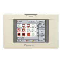
intelligent Touch Controller
5.2 Points of Installation
(Do not fail to use a round crimp terminal with reinforcing sleeve for safety wiring connection to the intelligent Touch
Controller.)
N, PF1, F2 N, PF1, F2
F1, F2F1, F2
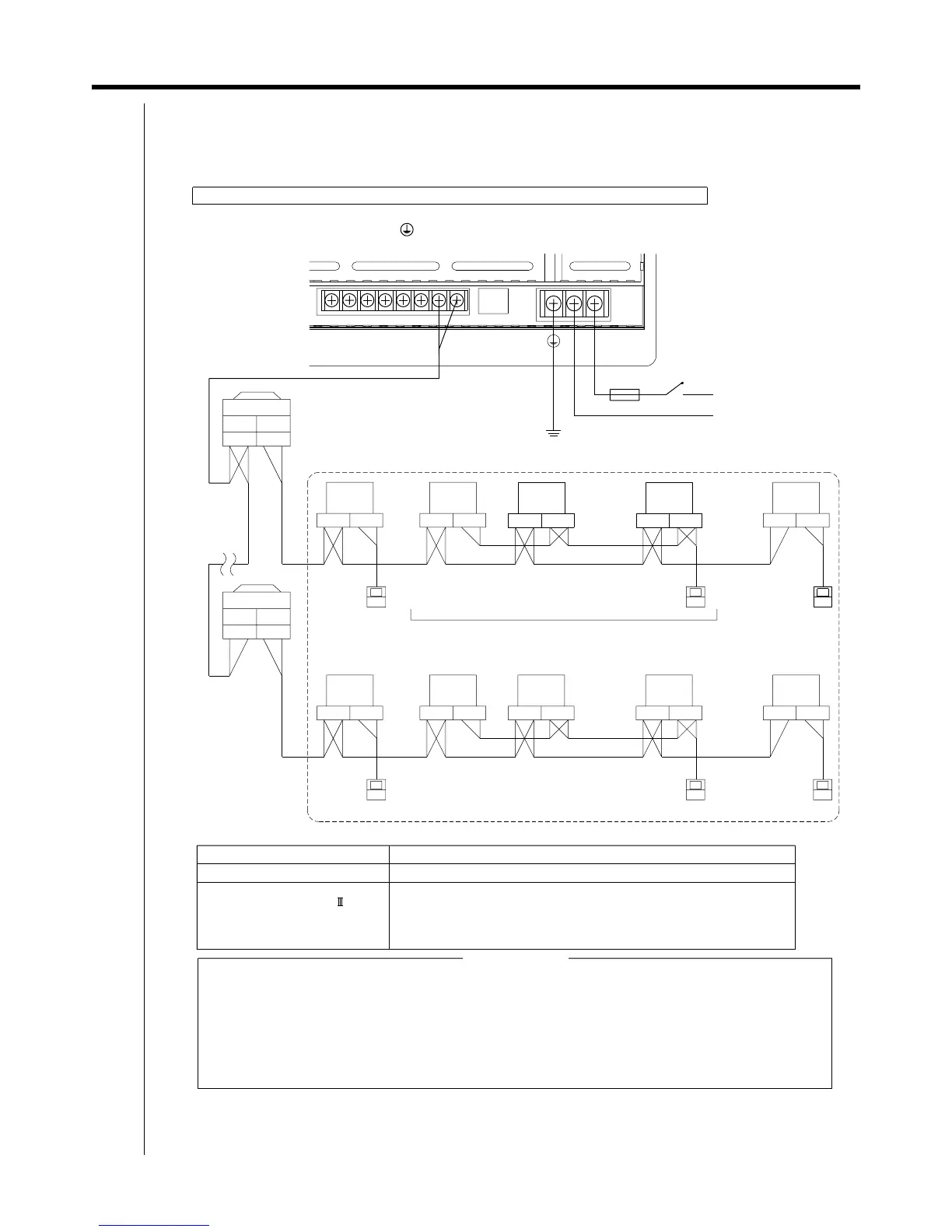
In order to perform centralized control of indoor units using this controller, connect the power wiring to terminals
L and N, earth wire to earth terminal and connecting wiring for DIII-NET communication of air-conditioner
(indoor unit and outdoor unit) to terminals F1 and F2 respectively as shown in the sketch below.
Wiring for power supply and Connecting wiring for DIII-NET communication of indoor units
F1F2COM Pi3Di1 COM Pi2 Pi1
1.25mm
2
•
Up to 16 units maximum
switch
Maximum up to 64 groups (128 units)
IN-OUT
0.75 - 1.25mm
2
vinyl cord or cable with sheath (2 wire)
---Up to 1000m maximum
(wiring length -- up to 2000m maximum)
(When shield cable is used, the wiring length is available up to 1500m.)
For the type of electric wire, refer to the design guide.
Grounding work
<< CAUTION >>
•
Don't fail to perform installation of Grounding work. Don't connect the grounding wire to any of gas pipe,
city water pipe, lightning rod, and telephone grounding wire.
Don't turn ON the power supply (front switch) until all the works are complete.
The connecting wiring for communication of indoor and outdoor units is a connecting wiring for the control.
Don't clamp these cables together with high voltage cables.
Failure to observe this instruction would cause control error.
Don't connect the power cable to F1, F2 terminal blocks. Wrong connection to these terminal blocks could
result in damage and burning of the centralized control devices and of the electric parts of the indoor and outdoor units.
This is very hazardous. Check each wired cable once more before turning ON the power switch.
•
Indoor unit
N, P
F1, F2
Indoor unit
N, P
F1, F2
Indoor unit
N, P
F1, F2
Indoor unit
N, P
F1, F2
Indoor unit
N, P
F1, F2
Indoor unit
Indoor unit
N, PF1, F2
Indoor unit
N, PF1, F2
Indoor unit
N, PF1, F2
Indoor unit
Outdoor unit
Power cable wiring
100V-240V
~
50/60Hz
10A
Fuse (10A)
Fuse
Connecting wiring for D -NET
communication of indoor and
outdoor units
OUT-OUT
F1, F2F1, F2
IN-OUT
Outdoor unit
OUT-OUT
•
When wiring, cut off the power supply (using a local switch) and do not apply power until all work has been finished.
N L
~
100-240V
Power supply

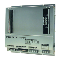

 To Next Page