184 3.1 Components
intelligent Manager
3. Installation and Electric Wiring
3.1 Components
The following parts are attached to this unit.
Make sure to check them before installation.
3.2 Part Name and Function
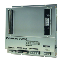
intelligent Processing Unit 1 set
INSTALLATION MANUAL 1 copy
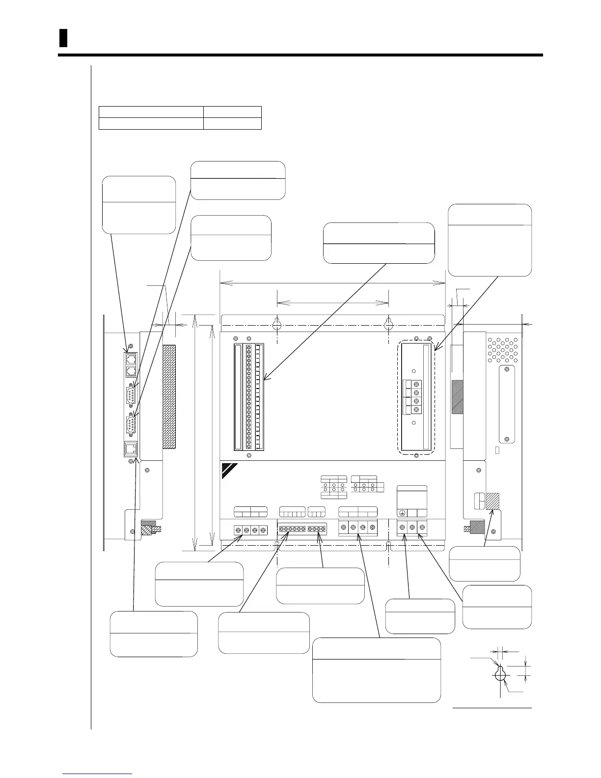
DIII-4
RCV
DIII-3
RCV
DIII BOARD
275 ± 1
10BASE-T
100BASE-TXRS232C-2
POWER
OFF ON
263 ± 1
(15)
(13)
Di BOARD
68.5 ± 2
260 ± 1
130 ± 1
F2F1 F1 F2
Turn this switch to
ON when using
Power supply switch
G10486G1252G 1511 1614GGGG3G 9713
Di
1
RS232C connector
-1
connect equipment
for RS232C
2
Do-2
T-
Terminal block for
communication with
air conditioners
R-
L
3
Make sure to connect
the earth wire
Terminal block for
communication with
air conditioners (This
terminal is not in
DAM602B52)
-2
RS485
ETHER
DIII
F1
Terminal block for
RS485 communication
Terminal block for
DIII-NET communication
ALRM
A2
When using AIRNET
service, connect it to
the telephone line
F2 G
PCMCIA
RCV
LINK
Terminal block for DIII-NET
communication (option)
AC100-240V
~
50/60Hz
Detailed drawing of fixing hole
Modem connector
for AIRNET
ALIVE
RS485
Connect the lines
with AC100-240V
Do-1
RxD
Do-1 : equipment for the contact
output is connected (No Voltage)
Do-2 : equipment for the contact
output is connected (No Voltage)
4
Connector for
PC communication
R+F2
B2
POWER
Terminal block for
contact input (No Voltage)
Terminal block for
contact input (No Voltage)
connected to PC (HUB)
G1
ETHER
BACKUP
TxD
-2
connect equipment
for RS485
Power supply
terminal block
T+
N
B1
Terminal block for
contact output (No Voltage)
contact input in 4 points
is connected (No Voltage)
connect equipment
for RS232C
A1
contact input in 16 points
is connected (No Voltage)
Di
-1
F1
RS232C connector
Earth terminal block
RS232C
DAIKIN D-BACS
DIII-3 DIII-4
DIII-1 DIII-2
CPU
R2.25
4.5
9
φ 10
PHONE