142 1.7 Initial Setting
Control Devices
1.7 Initial Setting
Setting (1) through (3) are initialized when power is turned ON, therefore complete settings BEFORE activating the
power.
(The positions of connectors and switches used for settings in this section are shown in Fig. 1.)
(1) Connector for setting master controller (X1A) (Provided with connector at factory set)
• When using only 1 central remote controller, do not disconnect the connector for setting master controller. (Use the
unit with the connector in the state in which it was delivered.)
• When using multiple central remote controllers, or using the central remote controller in conjunction with the optional
controllers for centralized control, makes settings as indicated in the below table.
(Remove this connector when using this controller in conjunction with power consumption counting unit, parallel interface,
and data station.)
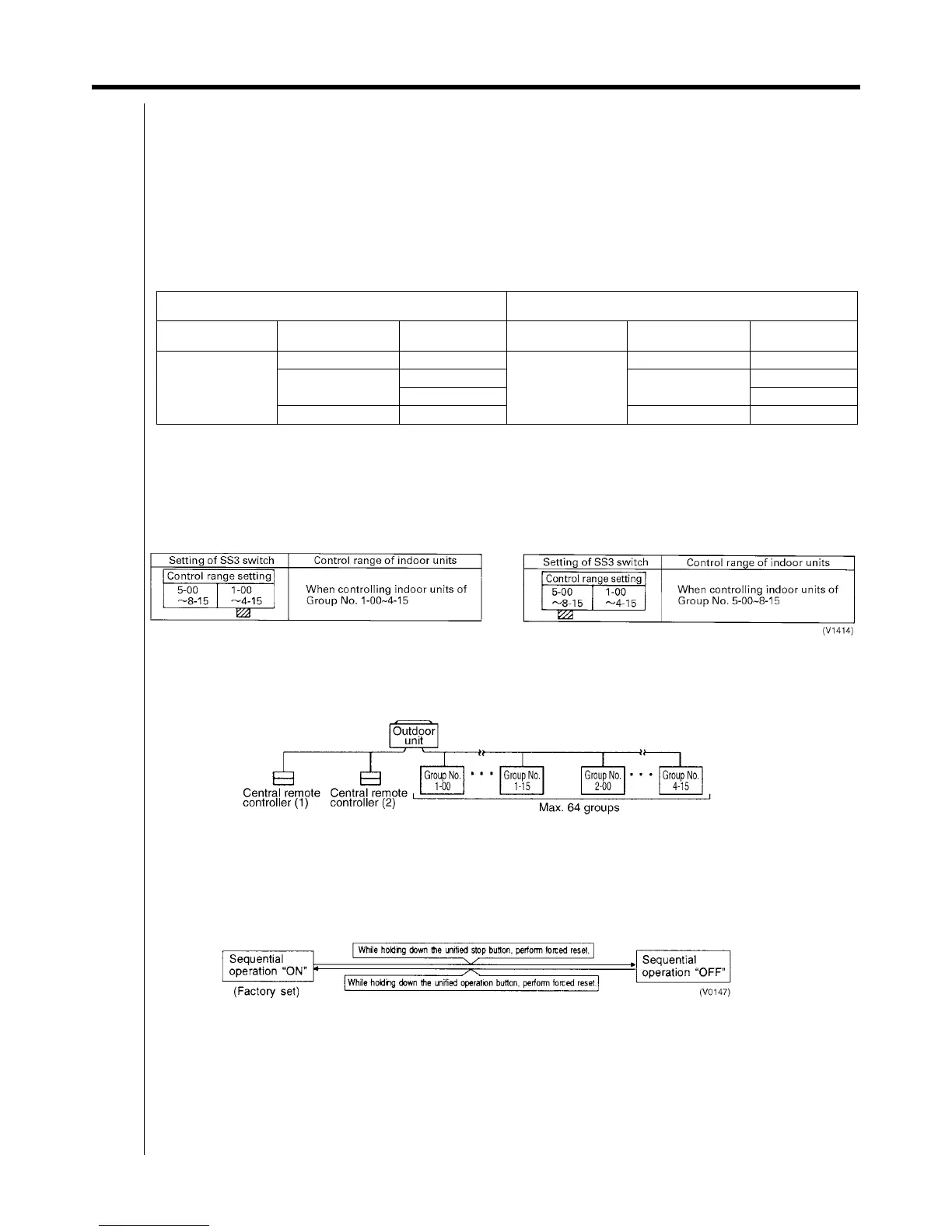
(2) Address setting
Two central remote controllers can be used as shown in “SYSTEM CONFIGURATION” to control anywhere up to a
max. 128 groups of indoor units. In this case, group address must be set. This is done with the switch for setting each
address (SS3).
(3) MAIN/SUB changeover switch setting
With two central remote controllers, centralized control (indoor units) is possible from different locations. In this kind of
set-up, it is necessary to set the MAIN/SUB changeover switch.
One of the two central remote controllers (1) · (2) is set to “MAIN” while the other is set to “SUB”
(4) Setting of the sequential operation function
The central remote controller is equipped with a sequential operation function that sequentially turns indoor units on in
2-second intervals during unified operation. (Sequential operation is factory set to “ON.”) To switch sequential
operation ON or OFF, set as follows.
Note:
The sequential operation function is designed to reduce the load on the power supply equipment, but does not guarantee
that compressors will not be started simultaneously. You cannot therefore count on a capacity reduction effect by power
supply equipment breaker selection.
Pattern of Connection of Optional Controllers for Centralized
Control
Connector for Setting Master Controller (X 1A) Setting
Central Remote
Controller
Unified ON/OFF
Controller
Schedule Timer Central Remote
Controller
Unified ON/OFF
Controller
Schedule Timer
1 to 4
——
Set one to “Used” and
all the rest to “Not
used”.
——
1 to 16
—
Set all to “Not used”.
—
1 “Not used”
— 1 — “Not used”