2.6 Electric Wiring 155
Control Devices
2.6 Electric Wiring
All wiring, components and materials to be procured on the site must comply with the applicable local and national
codes.
Use copper conductors only.
All field wiring and components must be provided by licensed electrician.
Unit shall be grounded in compliance with the applicable local and national codes.
Fit the power supply wiring with a fuse and a switch.
After wiring work, check power to the equipment shuts OFF when switch is shut OFF.
Wiring Specification
Notes:
1. The size of power supply wiring must comply with the applicable national and local codes.
Connect the wiring between indoor and outdoor units, indoor/outdoor units and power supply, and indoor units and
remote controllers.
For details, refer to the installation manuals of indoor and outdoor units.
2.7 Confirming Operation
Before starting test operation, supply power to the indoor units, outdoor units, and unified ON/OFF controller and press
the ON/OFF button. If the operation lamp flashes, it indicates a malfunction in the indoor unit of the applicable group.
If the display of “ ” flashes, it indicates a malfunction in the optional controllers for centralized control. Check for
such malfunctions.
Notes:
For test operation of indoor and outdoor units, refer to the installation manual attached with the outdoor unit.
After turning the power supply ON, if the unit does not accept operation for two minutes or more with the display of
“ ” flashing, check the following points.
Check that setting of the connector for setting master controller is correct.
Check that the group No. for centralized control has been set.
1P162827
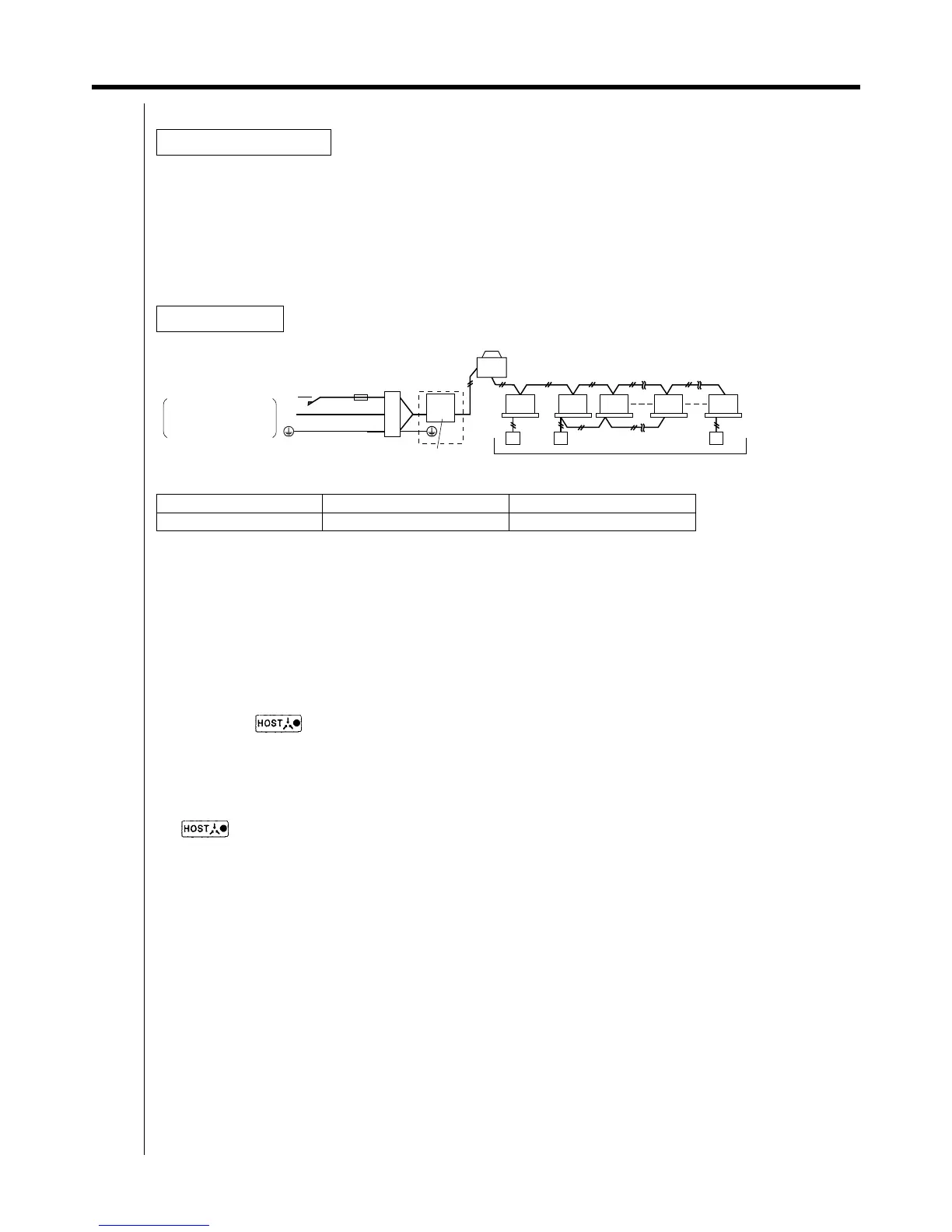
General Instructions
Wiring Outline
Type Size
Power Supply Wiring H05VV-U3G (Note 1)
Max. 16 groups
Power supply
~
100-240V 50/60Hz
Unified ON/OFF controller
Electric parts
box
(KJB212AA)
Fuse
(15A)
Switch
F1,F2
F1,F2
F1,F2 F1,F2 F1,F2 F1,F2
L
N
Outdoor
unit