Do you have a question about the Daikin D-BACS and is the answer not in the manual?
Provides an overview of the DAIKIN Building Air-conditioning Control System (D-BACS) and its integration capabilities.
Details the general overview of the D-BACS system, including project scale and targeted applications.
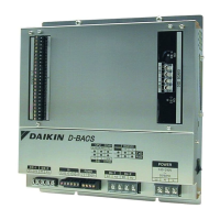
Lists the D-BACS system equipment and provides main specifications and functions for each component.
Explains the various functions and capabilities of the centralized controllers within the D-BACS system.
Provides a list of DAIKIN models that are applicable and can be connected to the DIII-NET system.
Details the design standards for DIII-NET, including terminal numbers and connection methods.
Specifies the number of units that can be connected to the system, including flow charts for determination.
Explains the concepts of grouping and zoning for unit control, including definitions and patterns.
Discusses the combination of multiple central remote controllers like DCS302CA61, DCS301BA61, and DST301BA61.
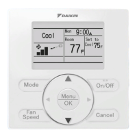
Lists indoor units and their corresponding individual operation remote controllers for VRV and HRV systems.
Provides dimensional information for various types of remote controllers, including wired and wireless models.
Details the functions available for different remote controllers, including BRC1C62 and Simplified Remote Controller.
Explains how to perform field settings on various remote controllers, such as BRC1C62 and wireless models.
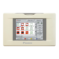
Identifies and describes the part names and functions of the intelligent Touch Controller.
Details the system configuration for the intelligent Touch Controller, including system outline and double controller setups.
Provides information on electric wiring for the intelligent Touch Controller, including terminal descriptions and examples.
Explains the web access function, allowing remote management of air conditioning systems via LAN.
Details the function, system configuration, specifications, and initial settings for the Central Remote Controller.
Covers the function, system configuration, specifications, and initial settings for the Unified ON/OFF Controller.
Explains the function, system configuration, specifications, and initial settings for the Schedule Timer.
Provides an overview of the intelligent Manager, including its features, specifications, and functions.
Details the system design for the intelligent Manager, covering configuration, required devices, and wiring diagrams.
Covers the installation process and electric wiring requirements for the intelligent Manager components.
Outlines the features, system, specifications, components, wiring, and functions of the BACnet Interface.
Provides wiring examples for the BACnet Interface, including connections for DMS502B51 and optional boards.
Provides a general introduction to LONWORKS Network functions and specifications for Daikin A/C control.
Details the system configuration for LONWORKS, including A/C units to be monitored and address setting.
Explains the functions of the LON interface, including overview of functions and applicable models.
Covers electric wiring connections and examples for the LONWORKS interface.
Highlights key design points related to control, including system configuration, hardware, and restrictions.
Outlines the workflow for implementing LONWORKS interface, from inquiry to test run.
Provides a guide to P.P.D. design, including system architecture, design precautions, and explanations.
Details the use of the intelligent Touch Controller with P.P.D. software and PCMCIA for power distribution.
Lists various system adaptors, including Unification Adaptor, Wiring Adaptors, and External Control Adaptors.
Details adaptors for indoor units and other equipment, such as SkyAir Interface and Wiring Adaptors.
Describes the function, part names, installation, and wiring of the Dio Unit for external connections.
Explains the function, part names, installation, and wiring for the Di Unit, enabling connection of other facilities.
Details the function, part names, installation, and wiring for the Ai Unit, supporting various analog inputs.
| Brand | Daikin |
|---|---|
| Model | D-BACS |
| Category | Control Systems |
| Language | English |