152 2.4 Part names and Functions
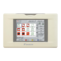
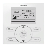
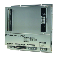
Control Devices
NOTE 1. When not using the optional accessory applicable to EMI (KEK26-1A), connect the power supply wiring directly
to the unified ON/OFF controller.
F1 F2
F1 F2
F1 F2
F1 F2
F1 F2
P1 P2
F1 F2
P1 P2
F1 F2
P1 P2
F1 F2
P1 P2
F1 F2
P1 P2
F1F2
L N
L N L N
TO IN/D UNIT
TO OUT/D UNIT
Outdoor unit
TO IN/D UNIT
TO OUT/D UNIT
Outdoor unit
Indoor unit Indoor unit Indoor unit
Indoor unit
TO OUTDOOR UNIT
Indoor unit
Power supply (NOTE 1)
~
100-240V 50/60Hz
1 For connecting indoor unit (F1, F2)
2 Forced OFF input (T1, T2)
While the forced OFF input (no voltage contactor, for micro current)
is ON (energized), all the connected indoor units are stopped and
can not be operated.
Use only contactors which guarantee the minimum applicable load
DC16V, 10mA.
3 For schedule timer (D1, D2)
Power can be supplied to the schedule timer (DST301BA51•61
optional accessory). For details, refer to the installation manual of
the schedule timer.
Wire 2 and 3 only when necessary.
NOTE) Use instantaneous contactor of
over 200msec. energizing time,
when necessary.
CONTROL TERMINAL STRIP
DC16V
T1
T2
F1F2
L N
L N L N
Electric
parts box
(KJB212AA)
Optional accessory
applicable to EMI
(KEK26-1A)
1
F1 F2 T1 T2 D1 D2
2 3
 Loading...