292 1.3 <DTA104A61 / DTA104A62 / DTA104A53> External Control Adaptor for Outdoor Unit (Must be Installed on Indoor Units)
Adaptor
[Input signal]
Constant a contact
Input current is approx. 10 mA per contact.
For the relay contact, use a weak current contact.
[Outside wiring specifications]
Recommended wiring: 0.75-2 mm
2
sheathed wire
Wiring length: Within 150 m
Keep a minimum 50 mm from power supply wiring to prevent malfunction.
Demand input terminal
Short circuit between (Demand 1) - (C)...As a guideline, demand should be about 70%.
Short circuit between (Demand 2) - (C)...As a guideline, demand should be about 40%.
Short circuit between (Demand 3) - (C)...Forced thermo OFF
Low-noise input terminal
When terminals are short-circuited during cooling, capacity save (outdoor unit fan low-speed turn, compressor frequency
control) is carried out.
use only at night when load is slight.
How to set demand control in the field
1. Outdoor unit field setting
Setting mode 1...Turn ON low noise control as explained in the outdoor unit’s service manual.
Setting mode 2...Match low noise and demand addresses to the external control adaptor address.
2. External control adaptor settings
Function switch (SS1)
Set SS1 to either “BOTH” or “DE”.
Address setting switch (DS1,DS2)
Match DS1 and DS2 to the low noise and demand addresses of the outdoor unit.
<Field settings >
Setting switches cannot be
switched unless the power is
turned on. Be sure, therefore,
to turn the power off after
switching the switches.
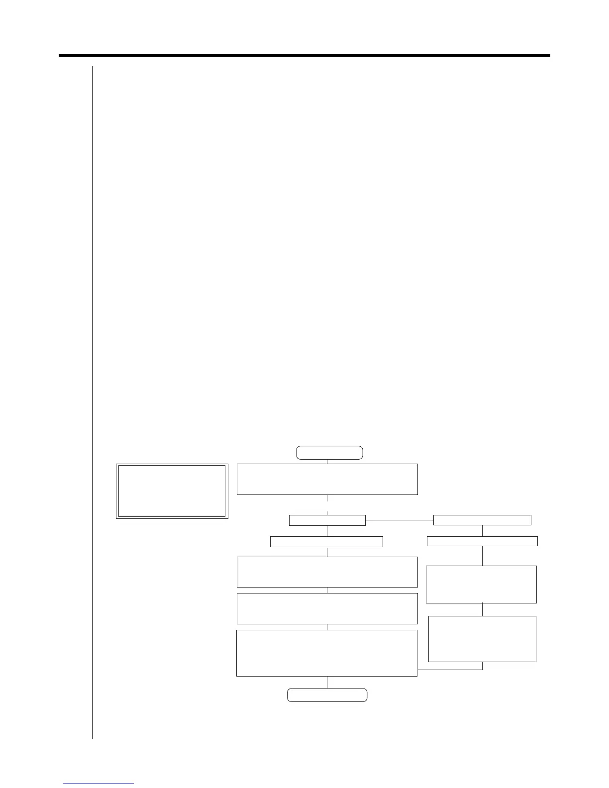
1. The contents of the various settings for unified switching of the operation mode
(cool, heat, fan) are as follows.
Grouping the outdoor units by each operation mode.
(Herein after refer to as "operation mode group").
Each group shall be required this adaptor.
Nominate the "MASTER" unit and "SLAVE"units per
operation mode group and set them on the outdoor
unit's PC board ass'y.
Designate and set outdoor units
as "MASTER" and "SLAVE".
(See the outdoor unit's
CAUTION ON OPERATION.)
Set SS1 of the PC board of the
outdoor unit set as "MASTER "
to "IN/D UNIT" (See the
outdoor unit's CAUTION
ON OPERATION.)
Set SS1 of the PC board of the outdoor unit set as
"MASTER" to "OUT/D UNIT". (See the outdoor
unit's CAUTION ON OPERATION.)
Set the 5-bit COOL/HEAT address of the adaptor and
outdoor units. (See Note 1.)
Set the service/mode for the outdoor units by operating
the switches on the PC board ass'y. (See fig. 2.)
The adaptor is set by DS1, 2. (See fig.1.)
COOL/HEAT selector
Indoor unit remote controller
Set SS2 of the adaptor to "OFF".
Set SS2 of the adaptor to "OFF".
<Means of switching operation mode?>
Field setting start
Field setting complete
Note 1: Match the address of the adaptor and
outdoor units for each control unit.