1.7 Ai Unit (DAM101A51) 323
Adaptor
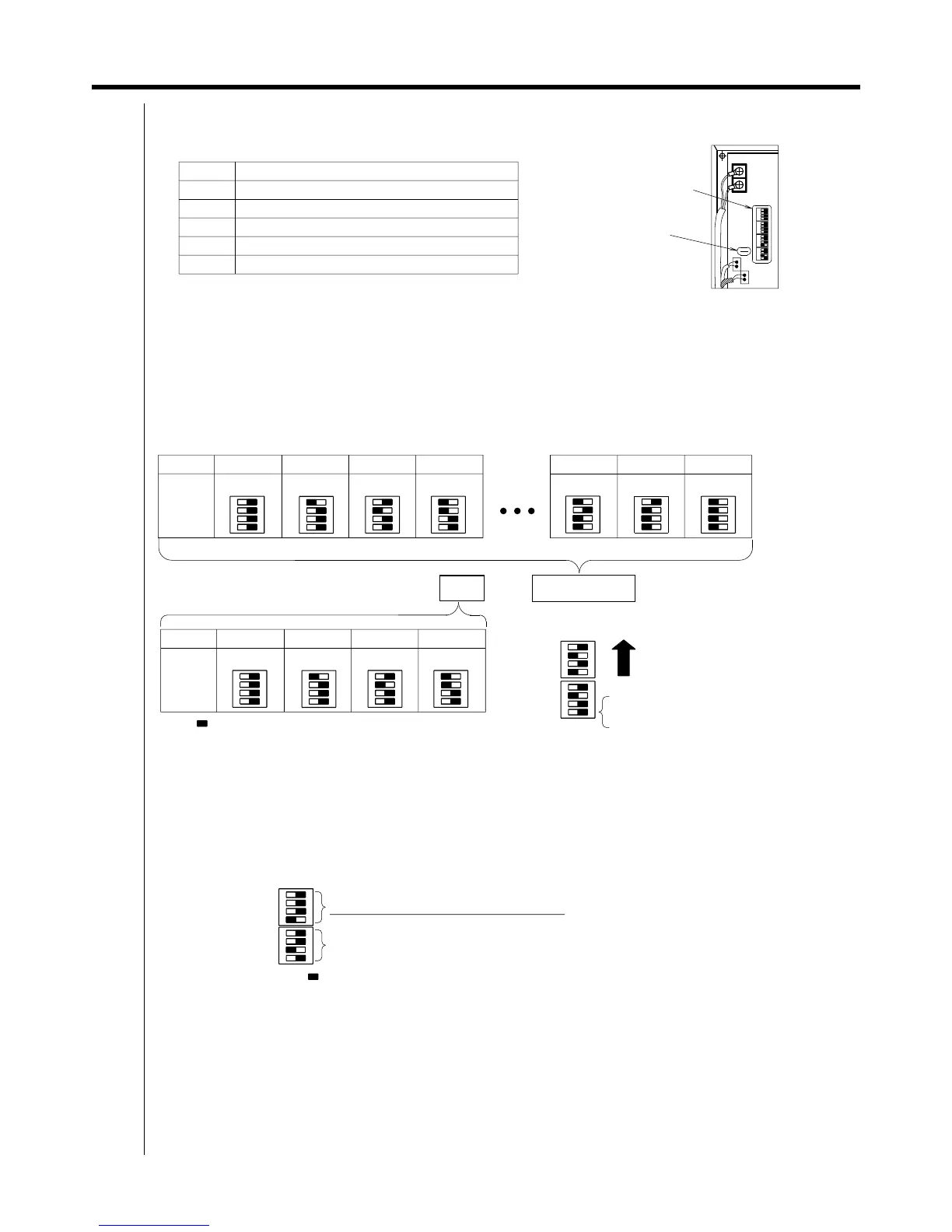
4. Setting the dipswitches and cutting the jumper line
DS1 and DS2 (DIII-NET communication address) settings
DS3 and DS4 (sensor - related) settings
DIII-NET Address
—
Ex: 3-10
It should always be OFF.
It should always be OFF.
When using multi - purpose sensors it should always be ON.
It should always be ON.
ON OFF
Number
DS3
JP6
It should always be OFF.
It should always be OFF.
It should always be ON.
It should always be OFF.
∗1
ON OFF
DS2
3
ON OFF
The switch at the
very end of DS1
should always be set off.
00
DS1
4
Meaning
15
2
∗2
The " " symbol indicates switch knob position.
DS4
Dipswitches
DS1 to DS4
ON OFF
13
Dipswitch and jumper location
When using multi-purpose sensors, cut the main jumper line.
DS4
ON OFF
Enabling and disabling the sensor
∗2
03
Upwards when
attached
ON OFF
ON OFF
ON OFF
ON OFF
DS3 should only have its setting changed if locally-procured sensors are being used.
When using locally procured sensors, set the third switch from the front on.
(The factory default settings are for not using multi-purpose sensors.)
NB: When using multi-purpose sensors, cut the jumper line
at the same time as the settings
are being done.
There is no need to change the factory default setting for DS4.
1
DS1
ON OFF
01 02
ON OFF
14
∗1
ON OFF
DS1
Setting DS1 and DS2" sets the DIII-NET communication address.
Set the DIII-NET communication address between 1 - 00 and 4 - 15.
Normally only one address is used per unit. The factory default is 1 - 00.
However, when using the settings below in
to use multi-purpose sensors, two addresses are used
per unit. (For example, if the address is set to 2 - 10 using the DS1 and DS2 settings, 2 - 10 and 2 - 11
are thereby used and cannot be set on other AC units.
If the setting is for using the multi-purpose sensors, do not set DS1 and DS2 to 4 - 15. The multi-purpose
sensor detection data cannot be properly monitored by i-Manager.)
The " " symbol indicates switch knob position.
DS2
Dipswitch settings for each address
Switching sensor uses
DS2
Jumper line to cut when
using multi-purpose
sensors: JP6
DS3
ON OFF
Meaning of each dipswitch and jumper line
DIII-NET Communication address last digit
DIII-NET Communication address first digit
 Loading...