2.5 <DTA103A51> Wiring Adaptor for Other Air Conditioners 345
Adaptor
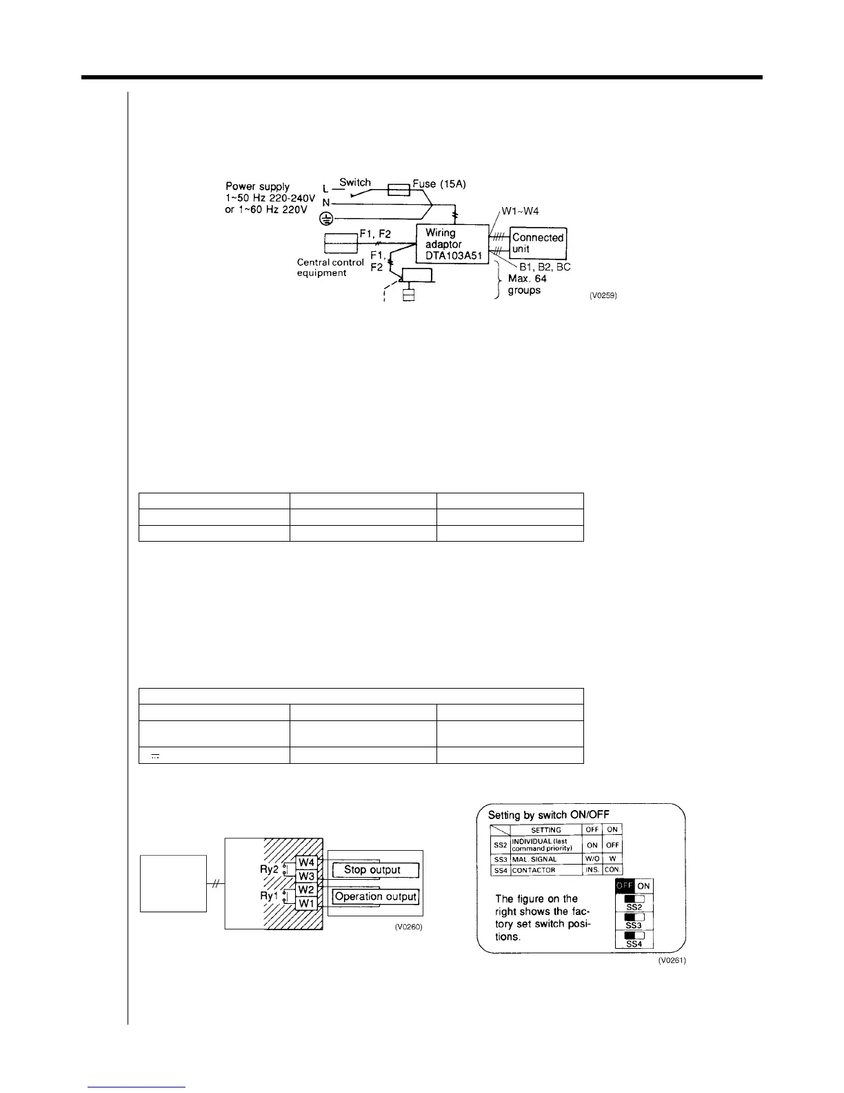
2.5.4 Electric Wiring Work
<Wiring Requirements>
1. Wire between the adaptor and central control equipment (F1, F2)
2. Wire to the connected units and set all switches. ... For details, refer to WIRING TO CONNECTED UNITS.
3. Wire to the power supply. ... For details, refer to POWER SUPPLY WIRING.
C : 2PA53853
<General Instructions>
All wiring, components and materials to be procured on the site must comply with the applicable local and national
codes.
Use copper conductors only.
All field wiring and components must be provided by licensed electrician.
Unit shall be grounded in compliance with the applicable local and national codes.
Fit the power supply wiring with a fuse and a switch.
After wiring work, check power to the equipment shuts OFF when the switch is shut OFF.
<Wiring Specification>
Note:
1. Select the size in electric wire in accordance with the local and national standards.
2. You can use the shielded wire, sheathed vinyl cord or cable (2 conductors). See the installation manual of the optional
controllers for centralized control to be connected for further details.
<Wiring to Connected Units>
Control Output
Terminals W1 - W4 are non voltage contacts used in normal operation to output operation display (W1 and W2) and error
display (W3 and W4) signals.
Output modes include instantaneous output (INS.) and constant output (CON.). Mode is changed at the contactor switch
(SS4). (Factory set: INS)
C : 2PA53853
Type Size
Power Supply Wiring H05VV-U3G (Note 1)
Transmission Wiring (Note 2) 0.75 - 1.25 mm²
Ry1 and Ry2 Contact Specifications
Voltage Max. current Min. Current
1
~
50Hz 220-240V
1
~
60Hz 220V
2A 1mA
5-24V 3A 1mA
Equipment
F1F2BMS


 To Next Page