3.7 Wireless Remote Controller <BRC4C, 7C, 7E> 73
Remote Controllers
Names and Functions of the Operating Section
C : 3PA63363-13G
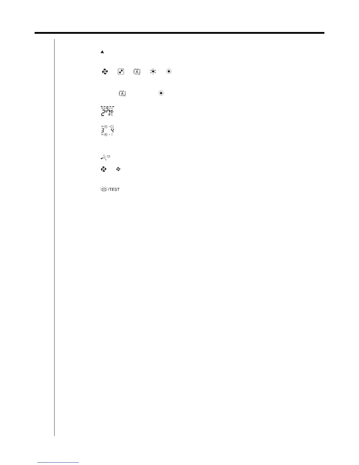
1 DISPLAY " " (SIGNAL TRANSMISSION)
This lights up when a signal is being transmitted.
2 DISPLAY " " " " " " " " " "
(OPERATION MODE)
This display shows the current OPERATION MODE.
For straight cooling type, " " (Auto) and " "
(Heating) are not installed.
3 DISPLAY " " (SET TEMPERATURE)
This display shows the set temperature.
4 DISPLAY " " (PROGRAMMED TIME)
This display shows PROGRAMMED TIME of the
system start or stop.
5 DISPLAY " " (AIR FLOW FLAP)
6 DISPLAY " " " " (FAN SPEED)
The display shows the set fan speed.
7 DISPLAY " " (INSPECTION /
TEST OPERATION)
When the INSPECTION / TEST OPERATION
BUTTON is pressed, the display shows the system
mode is in.
8 ON / OFF BUTTON
Press the button and the system will start.
Press the button again and the system will stop.
9 FAN SPEED CONTROL BUTTON
Press this button to select the fan speed, HIGH or
LOW, of your choice.
10 TEMPERATURE SETTING BUTTON
Use this button for SETTING TEMPERATURE
(Operates with the front cover of the remote
controller closed.)
11 PROGRAMMING TIMER BUTTON
Use this button for programming "START and / or
STOP" time. (Operates with the front cover of the
remote controller opened.)
12 TIMER MODE START / STOP BUTTON
13 TIMER RESERVE / CANCEL BUTTON
14 AIR FLOW DIRECTION ADJUST BUTTON
15 OPERATION MODE SELECTOR BUTTON
Press this button to select OPERATION MODE.
16 FILTER SIGN RESET BUTTON
Refer to the section of MAINTENANCE in the
operation manual attached to the inddor unit.
17 INSPECTION / TEST OPERATION BUTTON
This button is used only by qualified service persons
for maintenance purposes.
18 EMERGENCY OPERATION SWITCH
This switch is readily used if the remote controller
does not work.
19 RECEIVER
This receives the signals from the remote controller.
20 OPERATING INDICATOR LAMP (Red)
This lamp stays lit while the air conditioner runs. It
flashes when the unit is in trouble.
21 TIMER INDICATOR LAMP (Green)
This lamp stays lit while the timer is set.
22 AIR FILTER CLEANING TIME INDICATOR
LAMP (Red)
Lights up when it is time to clean the air filter.
23 DEFROST LAMP (Orange)
Lights up when the defrosting operation has started.
(NOTE)
1 For the sake of explanation, all indications are
shown on the display in Figure 1 contrary to
actual running situations.
1 Fig.1-2 shows the remote controller with the front
cover opened.
1 If the air filter cleaning time indicator lamp lights
up, clean the air filter as explained in the
operation manual provided with the indoor unti.
After cleaning and reinstalling the air filter, press
the filter sign reset button on the remote
controller. The air filter cleaning time indicator
lamp on the receiver will go out.