4.5 <KRCS01-1A> Remote Sensor 81
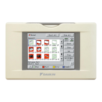
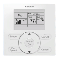
Remote Controllers
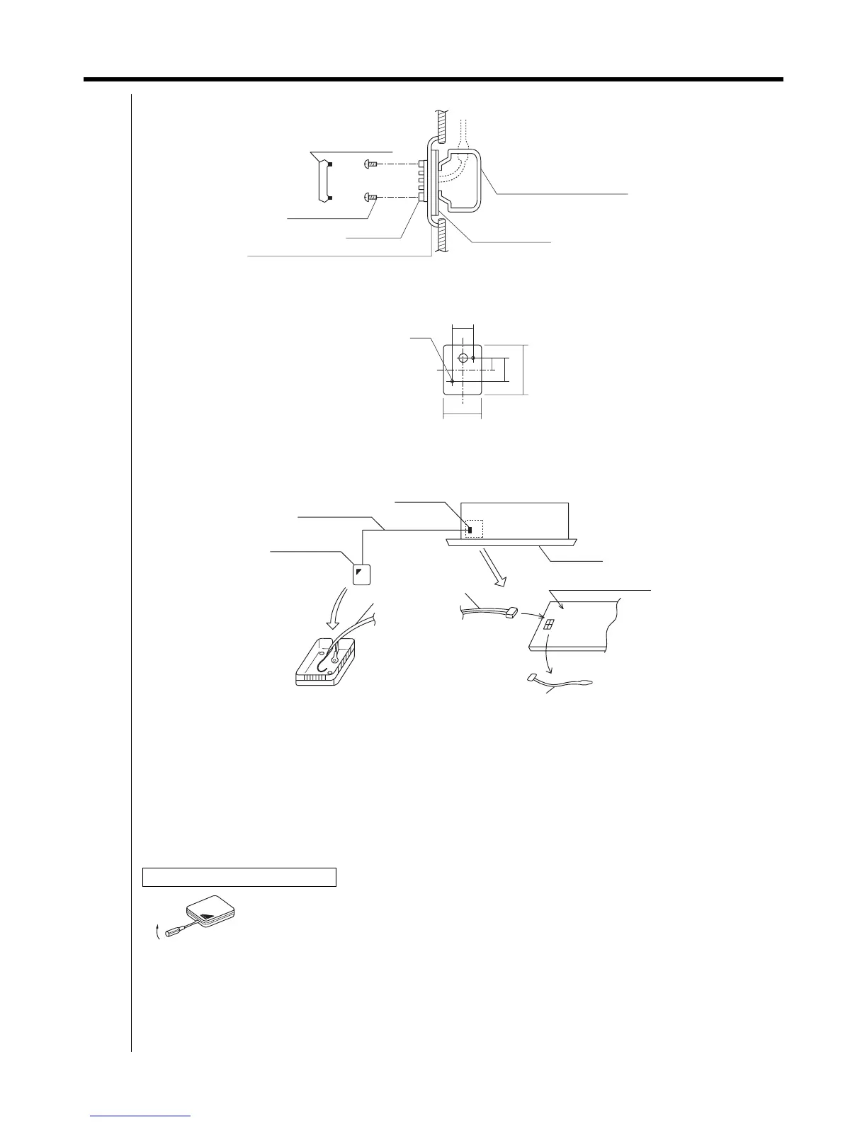
Embedded wiring
<3> Wiring guide
Use the extension cable provided to wire from the remote sensor to the electronic control unit in the indoor unit.
z Wire to the electronic control unit in the indoor unit by first removing the existing thermistor (inlet air temperature
sensor) and connecting the extension cable in its place.
(The existing thermistor is no longer required.)
z The position of the thermistor used for sensing the inlet air temperature is different according to the type of indoor unit.
Check the wiring diagram for the indoor unit to make sure that you do not accidentally remove the wrong wiring.
z
In the indoor unit switchbox, use the same wiring clamps for the extension cable as were used for the existing thermistor.
z If the extension cable is far too long, cut it to the appropriate length, strip the coating and fit the round crimp
terminals provided. (Do not cut the cable at the connector end.)
z Push the sensor box cover onto the sensor box.
<Cautions for wiring>
1. Install the extension cable so that it will not be affected by nearby power cables or similar sources of noise.
(Noise may cause malfunctioning.)
2. Make sure that wiring connections are correct and secure.
Poor contact at the connections may mean that the room temperature is sensed incorrectly and cause problems.
<4> Operation test after mounting the sensor
Conduct operation tests of cooling and heating after mounting the sensor and completing the wiring.
3P011730B
z Make sensor box mounting holes in a metal plate (sourced locally) as shown on the right.
Screw the sensor box firmly into position.
Warning: Make sure not to cover the air holes in the sensor box.
Removing the sensor box cover
Remove the cover from the sensor box using a flat screwdriver inserted in the slot in the sensor box
and the cutout in the upper case.
(Under normal circumstances, do not remove the cover from the sensor box.)
Sensor box cover
Mounting screws
Sensor box
Mounting frame
(Sourced locally)
Metal plate (single unit plate, no holes)
(Sourced locally)
Switch box
JIS-C8336 (single unit box)
(Sourced locally)
2-M4
32
21
42
(120)
(70)
Metal plate holes machined locally
Indoor unit
Indoor unit
electronic control unit
Existing thermistor
Extension cable
Extension cable
Connector
Screw terminal
connections