12.3 Dimensions
12.3.1 Mounting Dimensions, FR8–FR12
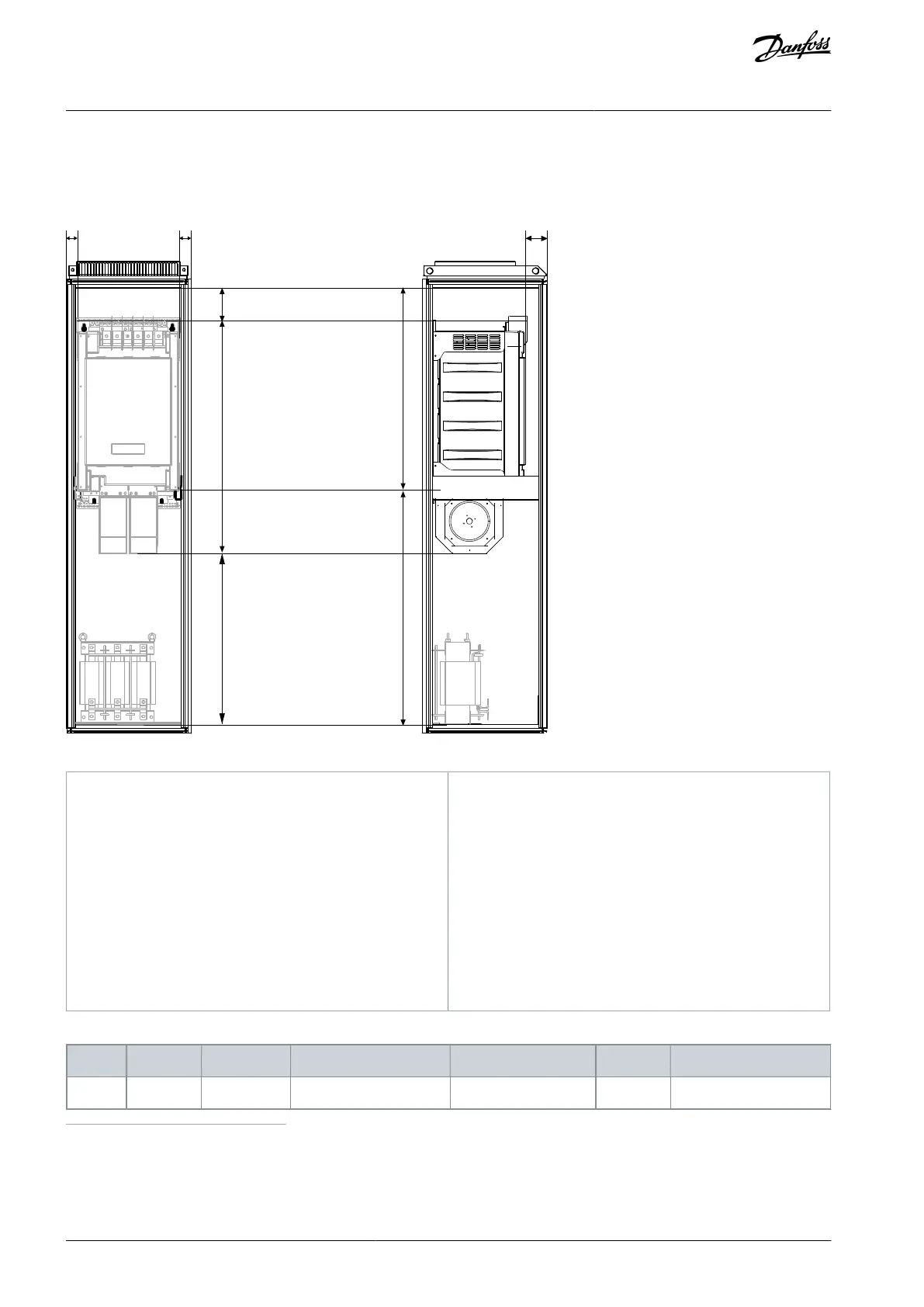
Illustration 75: Mounting Dimensions, FR8–FR12
Minimum distance to the side walls or adjacent
components. NOTE: No clearance needed between
the two cabinets in which the units of enclosure
FR12 are mounted.
Minimum distance from the top of the cabinet. This
space is needed for the power cables.
Minimum distance from the bottom of the enclo-
sure if the AC choke is installed at the bottom of the
enclosure.
Minimum distance from the cabinet door. It enables
the control unit to be installed in front of the power
unit.
Minimum distance from the mounting rails to top of
the cabinet.
Minimum distance from the mounting rails to the
bottom of the cabinet.
Table 29: Mounting Dimensions, mm
1
If the AC choke is installed in another location, the distance must not, however, be smaller than what is given in parentheses.
2
If the control unit is installed in any other location, the minimum distance from the door equals the number in parentheses.
AQ351737303996en-000201 / DPD00888120 | Danfoss A/S © 2023.09
Specifications
VACON® NXP IP00 Drive Modules
Operating Guide

 Loading...


