DigOUT:B.1 *)
DigOUT:B.2 *)
DigOUT:B.1 *)
RO1/1
RO1/2
RO1/3
RO2/1
RO2/2
RO2/3
Switching capacity
• 24 VDC/8 A
• 250 VAC/8 A
• 125 VDC/0.4 A
Minimum switching load
• 5 V/10 mA
Switching capacity
• 24 VDC/8 A
• 250 VAC/8 A
• 125 VDC/0.4 A
Minimum switching load
• 5 V/10 mA
Switching capacity
• 24 VDC/8 A
• 250 VAC/8 A
• 125 VDC/0.4 A
Minimum switching load
• 5 V/10 mA
Switching capacity
• 24 VDC/8 A
• 250 VAC/8 A
• 125 VDC/0.4 A
Minimum switching load
• 5 V/10 mA
RO1/1
RO1/2
RO1/3
RO2/1
RO2/2
TI1+
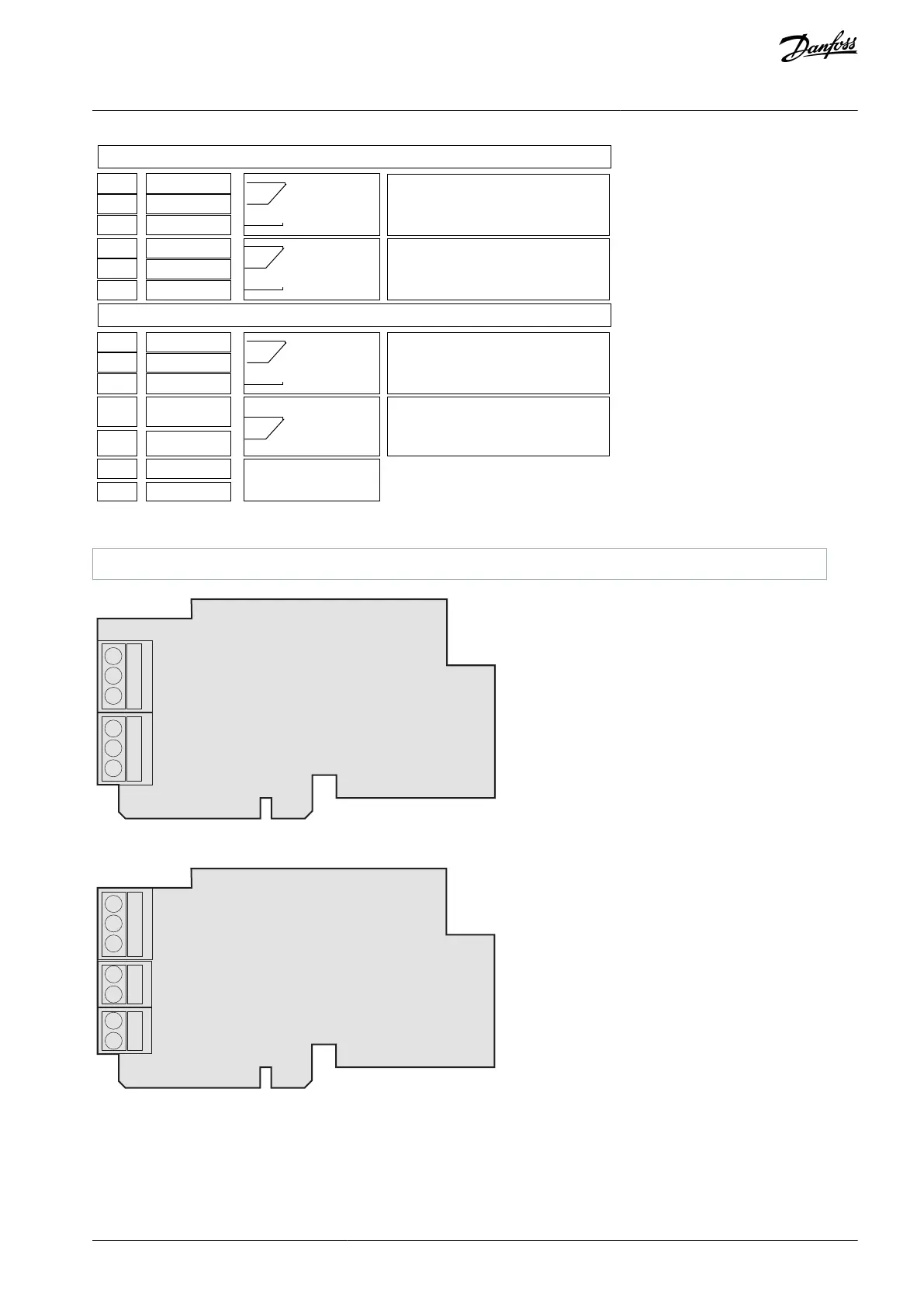
Illustration 58: Control Terminal Signals on Relay Boards OPTA2 and OPTA3
Parameter reference on control panel and NCDrive.
Illustration 59: OPTA2
Illustration 60: OPTA3
7.4 Fiber Cable Connections
When optical cables are used to link the power unit and the control board, a special Optical Cable Adapter Board connected to the
control board D-connector is used.
AQ351737303996en-000201 / DPD00888 | 75Danfoss A/S © 2023.09
Control Unit
VACON® NXP IP00 Drive Modules
Operating Guide

 Loading...


