•
Related Links
Jumper Selections on the OPTA1 Basic Board
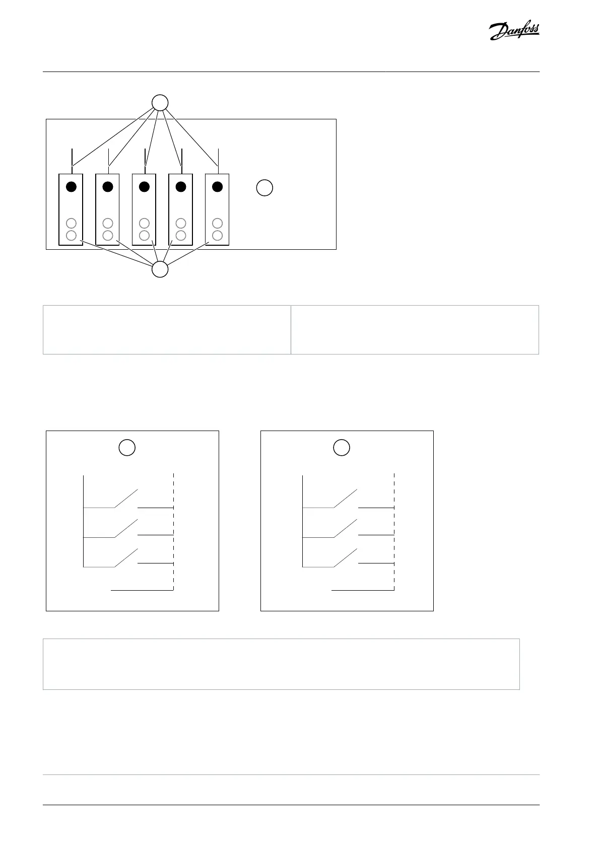
Illustration 54: Maximum Loads on +24 V/EXT+24 V Output
7.3.2.1 Digital Input Signal Inversions
The active signal level is different when the common inputs CMA and CMB (terminals 11 and 17) are connected to +24 V or to
ground (0 V).
The 24 V control voltage and the ground for the digital inputs and the common inputs (CMA, CMB) can be internal or external.
e30bg015.10
DIN1
+24V
GND
DIN2
DIN3
CMA
+24V
GND
DIN1
DIN2
DIN3
CMA
Illustration 55: Positive/Negative Logic
Positive logic (+24 V is the active signal) = the input is active when the switch is closed.
Negative logic (0 V is the active signal) = the input is active when the switch is closed. Set the jumper X3 to the
position 'CMA/CMB isolated from ground'.
AQ351737303996en-000201 / DPD0088872 | Danfoss A/S © 2023.09
Control Unit
VACON® NXP IP00 Drive Modules
Operating Guide

 Loading...


