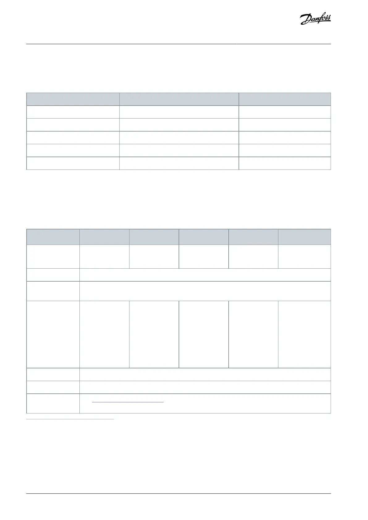
5.2.4 Temperatures Measured during Test Run
The following table shows the temperatures measured during a test run of a 520 A/400 V unit with nominal load at 50 Hz frequency.
The test unit was installed in a Rittal TS8 enclosure following the guidelines described in this manual.
Table 9: Temperatures Measured during an Accepted Test Run
Temperature in °C (in °F)
5.3 Cabinet Requirements for FR8–FR12
VACON® NXP IP00 power units of enclosures FR8–FR12 can be installed in cabinets. The cabinets have to meet the following re-
quirements.
The AC drives can be installed in any enclosure that fulfills these requirements. In the illustrations in this manual, Rittal TS8 is used as
an example enclosure.
Table 10: Cabinet Requirements for FR8–FR12
1800 mm (70.87 in) if the AC choke is installed beneath the power unit, otherwise minimum 1500 mm
(59.06 in)
Mechanical require-
ments: Total weight
of equipment the
cabinet must be
able to support (if
the power unit and
the AC choke are in-
stalled in the same
cabinet).
This manual applies to IP21.
See 5.2.1 Ventilation of the Cabinet.
1
Minimum 490 mm (19.29 in) if the control unit is installed in another position than at the front of the power unit
5.4 Cabinet Requirements for FR13–FR14
The power section of enclosures FR13 and FR14 includes 2–4 non-generative front-end (NFE) units, AC chokes, inverter units, and
dU/dt-filters (required for FR14). Several cabinets are, therefore, needed. Here are some example installations and their cabinet re-
quirements.
The AC drives can be installed in any enclosure that fulfills these requirements. In the illustrations in this manual, Rittal TS8 is used as
an example enclosure.
AQ351737303996en-000201 / DPD0088832 | Danfoss A/S © 2023.09
Mounting the Unit
VACON® NXP IP00 Drive Modules
Operating Guide

 Loading...


