Minimum bending radius 50 mm
Power module 1 ASIC board
Power module 2 ASIC board
7.5 Installation of Option Boards
For information on how to install the option boards, see the option board manual or VACON
®
NX I/O Boards User Manual.
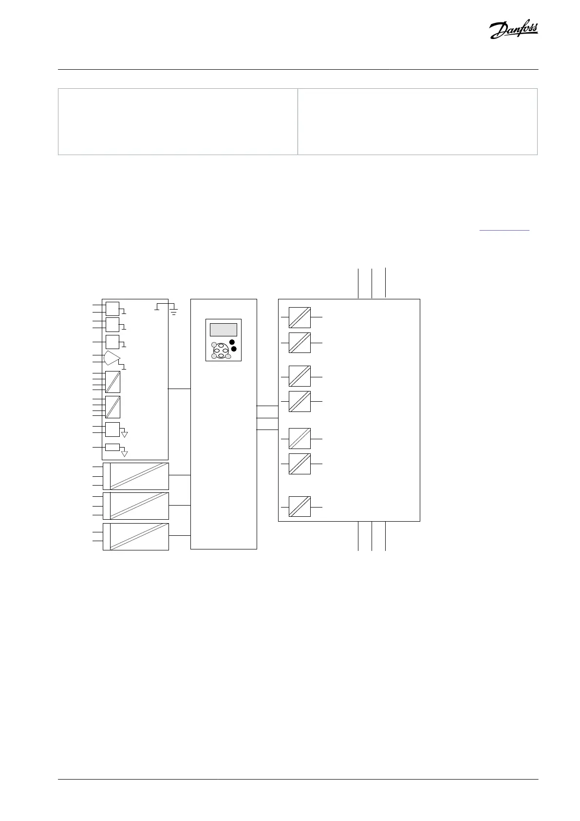
7.6 Galvanic Isolation Barriers
The control connections are isolated from mains. The GND terminals are permanently connected to I/O ground. See
Illustration 70.
The digital inputs on the I/O board are galvanically isolated from the I/O ground (PELV). The relay outputs are also double-isolated
from each other at 300 VAC (EN-50178).
Digital
input
group B
Analogue
output
Digital
output
AI2-
AI2+
AO2-
DO1
AO1+
DIN3
CMA
DIN6
CMB
DIN4...
RO1/2
RO1/3
RI1/1
RO2/2
RO2/3
TI1+
TI1-
RO2/1
Illustration 70: Galvanic Isolation Barriers
AQ351737303996en-000201 / DPD00888 | 83Danfoss A/S © 2023.09
Control Unit
VACON® NXP IP00 Drive Modules
Operating Guide

 Loading...


