9.
1.
2.
3.
4.
5.
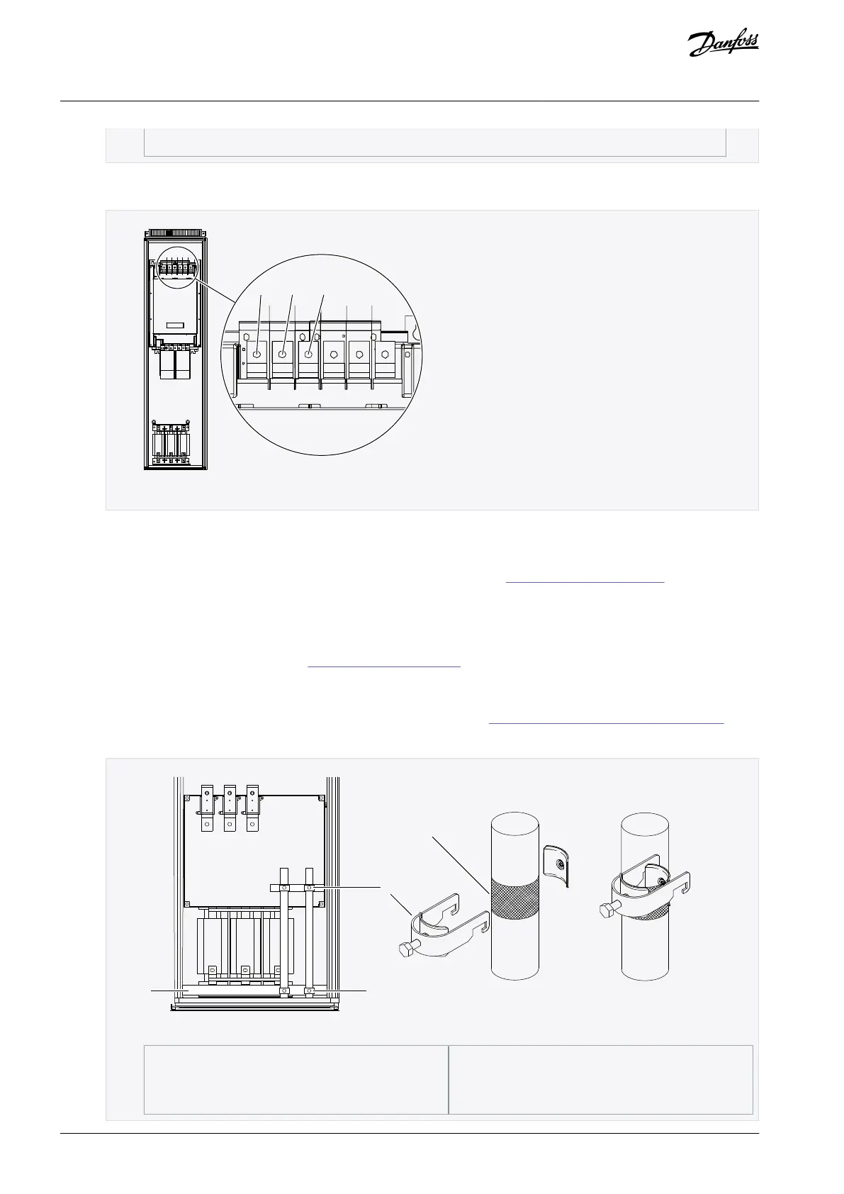
If an external brake resistor (option) is used, connect its cable to the appropriate terminal (R+/R–). Also make sure that the
AC drive is equipped with a brake chopper (indicated in the type code of the AC drive).
Illustration 35: Location of brake/DC terminals, FR10/FR12
6.7.5 Installing the Cables, FR11
Follow these instructions to install the cables.
For information on how to comply with the UL regulations in cable installations, see 6.1.2 UL Standards on Cabling.
Make sure that the delivery contains all necessary components.
Mount the units according to instructions in section Mounting the unit.
Procedure
Strip the motor and mains cables. See 12.6 Cable Stripping Lengths.
Remove the protection grids for the input terminals and the protection covers on the unit(s).
Pull the cable through the bottom plate of the cabinet and fix the PE conductor to the PE busbar of the cabinet.
Route the motor phase conductors through common mode chokes. See 6.5 Common-mode Chokes on Motor Cables.
To make a 360° connection with the grounding clamp for cable shield, expose the shield of motor cables.
Illustration 36: Installing EMC Grounding
AQ351737303996en-000201 / DPD0088860 | Danfoss A/S © 2023.09
Electrical Installation
VACON® NXP IP00 Drive Modules
Operating Guide

 Loading...


