7.
8.
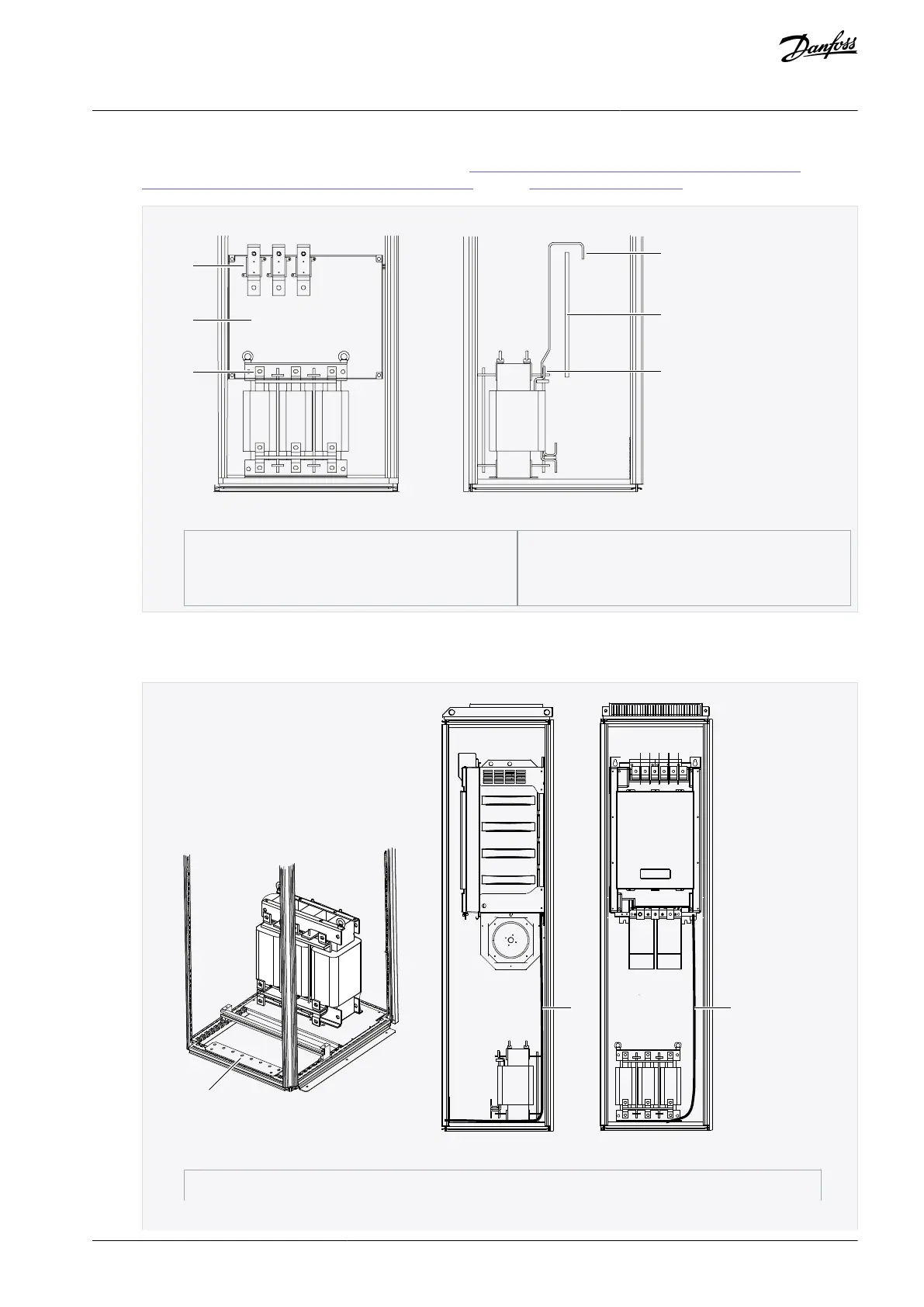
Install input terminals on the installation plate and connect them to the input terminals (the uppermost terminals) of the
AC choke using busbars or flexible busbars according to 12.4.2 Busbar and Terminal Dimensions for 380–500 V AC and
12.4.6 Busbar and Terminal Dimensions for 525–690 V AC. Also see 6.4 AC Choke Connections.
Illustration 33: Power Input Terminals and Busbars to AC Choke
Connect a grounding cable from the grounding connector at the lower right hand side of the power unit frame to the PE
busbar of the enclosure. Use a copper grounding cable with a cross-sectional area of at least 2*35 mm
2
per power unit,
which obeys the local regulations for grounding cables.
Illustration 34: Grounding the power unit, FR10/FR12
AQ351737303996en-000201 / DPD00888 | 59Danfoss A/S © 2023.09
Electrical Installation
VACON® NXP IP00 Drive Modules
Operating Guide

 Loading...


