Internal cable/phase [mm
2
]
1
70C PVC/90C XLPE Cu cable
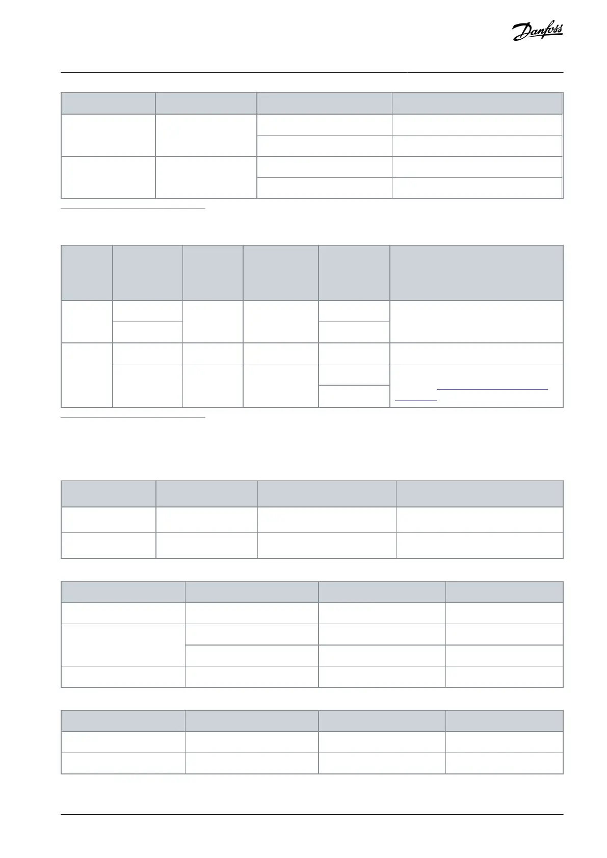
Table 47: Cable Sizes for 525–690 V AC, FR13–FR14
Busbar size/
phase
(1)
(AC
choke–NFE)
[mm]
Cable size/
phase (AC
choke–NFE)
[mm
2
]
Routing: Use symmetrical construction See
pictures in 5.4 Cabinet Requirements for
FR13–FR14.
1
Rigid copper connection
12.4.6 Busbar and Terminal Dimensions for 525–690 V AC
Table 48: Terminal Dimensions for 525–690 V AC, FR8–FR9
Table 49: Busbar Dimensions for 525–690 V AC, FR10–FR12
Table 50: Busbar Dimensions for 525–690 V AC, FR13–FR14
AQ351737303996en-000201 / DPD00888 | 137Danfoss A/S © 2023.09
Specifications
VACON® NXP IP00 Drive Modules
Operating Guide

 Loading...


