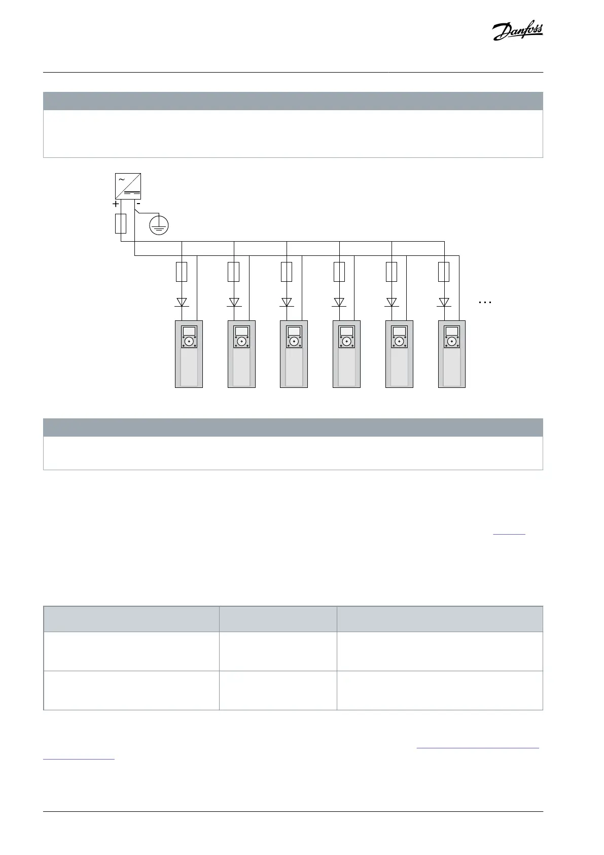
N O T I C E
If the AC drive is supplied with external 24 V DC power, use a diode in terminal #6 (or #12) to prevent the current to flow in
opposite direction. Put a 1 A fuse in 24 V DC line for each AC drive. The maximum current consumption of each drive is 1 A from
the external supply.
e30bg012.10
PE/GND
-G1
Ext +24VDC
Power Supply
#7 #6 #7 #6 #7 #6 #7 #6 #7
-Q2
3A
-Q3
3A
-Q4
3A
-Q5
3A
-Q6
3A
-F3
1A
gG/
Class CC
-F4
1A
gG/
Class CC
-F5
1A
gG/
Class CC
-F6
1A
gG/
Class CC
-F7
1A
gG/
Class CC
Illustration 52: Parallel Connection of 24 V Inputs with Many AC Drives
N O T I C E
The control unit I/O ground is not isolated from the chassis ground/protective earth. In the installation, consider the potential
differences between the grounding points. We recommend using galvanic isolation in the I/O and 24 V circuitry.
7.3 Control Unit Cabling
7.3.1 Selection of the Control Cables
The control cables must be a minimum of 0.5 mm
2
(20 AWG) shielded multicore cables. See more on the cable types in Table 16. The
terminal wires must be a maximum of 2.5 mm
2
(14 AWG) for the terminals of the relay board and 1.5 mm
2
(16 AWG) for other termi-
nals.
NOTE! The drive option with the integrated control unit does not require connecting of cables by the customer except for frame
FR12.
Table 21: Tightening Torques of the Control Cables
The tightening torque in Nm (in-lb)
Relay and thermistor terminals
7.3.2 Control Terminals on OPTA1
The figure shows the basic description of the terminals of the I/O board. For more information, see 7.3.2.2 Jumper Selections on the
OPTA1 Basic Board. For more information on control terminals, see VACON
®
All in One Application manual.
AQ351737303996en-000201 / DPD0088870 | Danfoss A/S © 2023.09
Control Unit
VACON® NXP IP00 Drive Modules
Operating Guide

 Loading...


