1.
2.
•
•
•
•
1.
2.
3.
4.
5.
Procedure
Fasten the mounting box with the control unit to a sidewall or to the frame of the enclosure.
The standard length of the connecting cable and the fiber optic cables is 2.3 m, so the control unit must be placed within
this distance from the power unit. Pay attention to the minimum bending radius of the fibre optic cables 7.4 Fiber Cable
Connections.
To ensure a proper grounding of the control unit assembly, we recommend that an extra grounding cable is drawn from
the mounting box and connected to the cabinet frame. Use a braided copper cable designed for high frequency signals.
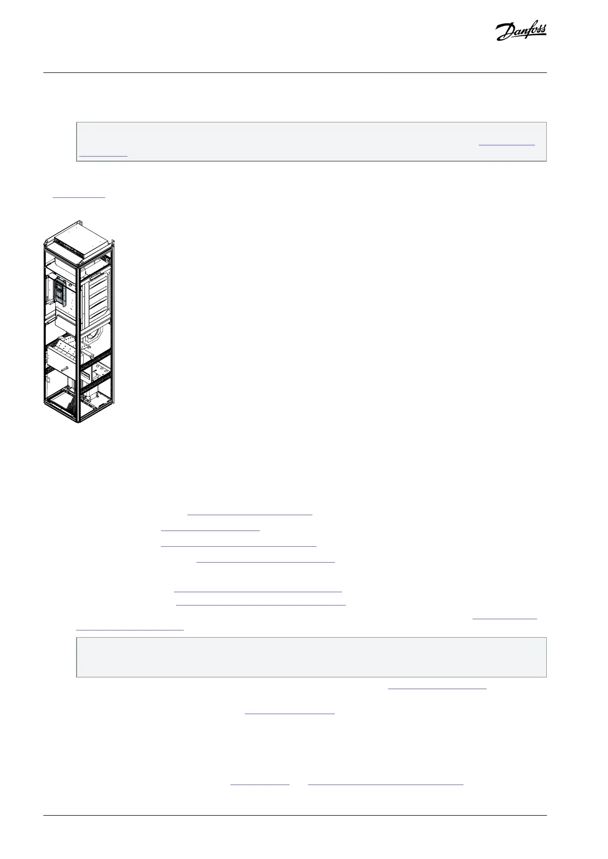
In Illustration 18, the control unit is mounted on a hinged assembly box (not included in standard delivery) in front of the power
unit, FR8–FR12.
Illustration 18: Mounted Control Unit, FR8–FR12
5.5.2 Installation Sequence for FR13–FR14
Use these instructions to install the VACON
®
NXP IP00 Drive Modules.
Check the following:
Environmental requirements, see 5.1 Environmental Requirements
Cooling requirements, see 5.2 Cooling Requirements
Cabinet requirements, see 5.4 Cabinet Requirements for FR13–FR14
The dimensions of the AC drive, see 12.3.3 List of Dimension Information
Procedure
Install the AC chokes, see 5.5.2.1 Mounting the AC Chokes, FR13–FR14.
Install the power unit, see 5.5.2.2 Mounting the Power Unit, FR13–FR14.
If the drive was ordered with the control unit separated from the power unit, install the control unit, see 5.5.2.3 Mounting
the Control Unit, FR13–FR14.
The VACON
®
NXP FR10–FR12 drive can be delivered with the control unit either integrally mounted on the power unit or
separated from the power unit and fixed to the mounting box. The mounting box can be installed to a sidewall or the
frame of the enclosure.
Make sure that there is sufficiently free space around the AC drive for cooling, see
5.2 Cooling Requirements. Some free
space is also necessary for maintenance.
Continue to the grounding and cabling, see 6.7 Installing the Cables.
5.5.2.1 Mounting the AC Chokes, FR13–FR14
This topic gives instructions on how and where to mount the AC choke in the cabinet for VACON® NXP IP00 Drive Module, FR13–
FR14.
Check the needed amount and type of chokes in 12.5 AC Chokes and 5.4 Cabinet Requirements for FR13–FR14.
AQ351737303996en-000201 / DPD0088840 | Danfoss A/S © 2023.09
Mounting the Unit
VACON® NXP IP00 Drive Modules
Operating Guide

 Loading...


