5.
1.
2.
Install a PE busbar, for instance, at the bottom front of the enclosure.
The PE busbar must be connected to external ground at the installation site according to local regulations.
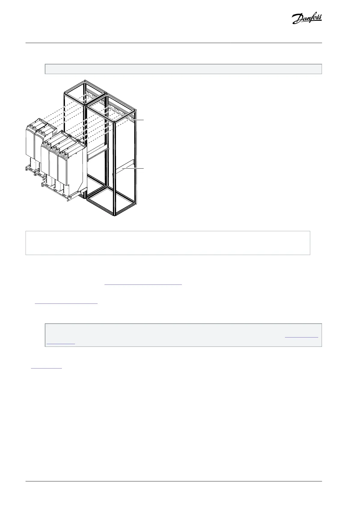
Illustration 21: Mounting the Power Unit, FR13–FR14
5.5.2.3 Mounting the Control Unit, FR13–FR14
The control unit for VACON
®
NX FR13–FR14 is always delivered separately. Use these instructions to mounting the control unit. For
dimensions of the control unit, see
12.3.6 Dimensions for Control Unit.
NOTE! If needed, connect the 24 V connecting cable and the fibre optic cables to the power unit before mounting the control unit.
See 7.4 Fiber Cable Connections.
Procedure
Fasten the mounting box with the control unit to a sidewall or to the frame of the enclosure.
The standard length of the connecting cable and the fiber optic cables is 2.3 m, so the control unit must be placed within
this distance from the power unit. Pay attention to the minimum bending radius of the fiberd optic cables 7.4 Fiber Cable
Connections.
To ensure a proper grounding of the control unit assembly, we recommend that an extra grounding cable is drawn from
the mounting box and connected to the cabinet frame. Use a braided copper cable designed for high frequency signals.
In Illustration 22, the control unit mounted on a hinged assembly box (not included in standard delivery) on the cabinet frame,
FR13–FR14
AQ351737303996en-000201 / DPD0088842 | Danfoss A/S © 2023.09
Mounting the Unit
VACON® NXP IP00 Drive Modules
Operating Guide

 Loading...


