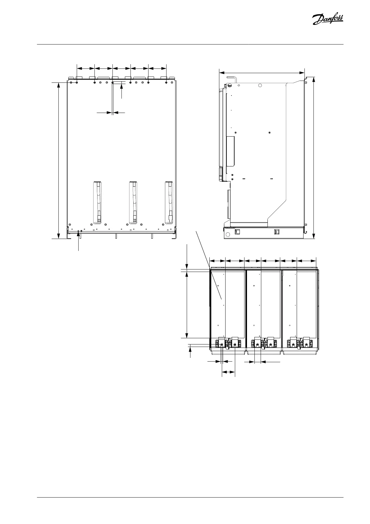
Home
Danfoss
Control Unit
VACON NXP IP00
Danfoss VACON NXP IP00 User Manual
5
of 1
of 1 rating
178 pages
Give review
Manual
Specs
To Next Page
To Next Page
To Previous Page
To Previous Page
Loading...
116
M8x25
116
9
116
116
15
A
430
17
103
123
109
123
109
123
16
13
85
40
1012.5
1049
116
553
e30bh454.10
Illustration 84: Dimensions for Inverter Unit FR13, Back View
12.3.5 Dimensions for AC Chokes
12.3.5.1 Dimensions for AC Choke, CHK0650
AQ351737303996en-000201 / DPD00888 | 129
Danfoss A/S © 2023.09
Specifications
VACON® NXP IP00 Drive Modules
Operating Guide
128
130
Table of Contents
Table of Contents
3
Introduction
10
Purpose of this Operating Guide
10
Additional Resources
10
Disposal
10
Manual Version
10
Type Approvals and Certifications
10
Safety
12
Safety Symbols
12
Danger and Warnings
12
Cautions and Notices
13
Product Overview
16
Intended Use
16
Package Label
16
Description of the Type Code
17
Enclosure Sizes
19
Available EMC Classes
20
Control Panel
21
Keypad
21
Display
22
Basic Menu Structure
23
Receiving the Delivery
24
Checking the Delivery, FR8-FR12
24
Checking the Delivery, FR13-FR14
24
Storing the Product
25
Lifting the Units
25
Lifting the AC Chokes
26
Using the Product Modified Label
27
Mounting the Unit
28
Environmental Requirements
28
Cooling Requirements
28
Ventilation of the Cabinet
29
Steering the Internal Airflow
30
Heat Dissipation
31
Temperatures Measured During Test Run
32
Cabinet Requirements for FR8-FR12
32
Cabinet Requirements for FR13-FR14
32
Installation Sequence
38
Installation Sequence for FR8-FR12
38
Mounting the AC Choke, FR10-FR12
38
Mounting the Power Unit, FR8-FR12
39
Mounting the Control Unit, FR8-FR12
39
Installation Sequence for FR13-FR14
40
Mounting the AC Chokes, FR13-FR14
40
Mounting the Power Unit, FR13-FR14
41
Mounting the Control Unit, FR13-FR14
42
Electrical Installation
44
Cable Connections
44
General Cable Requirements
44
UL Standards on Cabling
45
Cable Selection and Dimensioning
45
Fuse Selection
45
Principle of the Power Unit Topology
45
DC Supply and Brake Resistor Cables
46
EMC-Compliant Installation
47
Grounding
47
AC Choke Connections
49
Common-Mode Chokes on Motor Cables
50
Fuse Installation
50
Installing the Cables
51
Additional Instructions for Cable Installation
51
Installing the Cables, FR8
52
Installing the Cables, FR9
55
Installing the Cables, FR10/FR12
57
Installing the Cables, FR11
60
Installing the Cables, FR13/FR14
63
Control Unit
69
Control Unit Components
69
Control Voltage (+24 V/EXT +24 V)
69
Control Unit Cabling
70
Selection of the Control Cables
70
Control Terminals on OPTA1
70
Digital Input Signal Inversions
72
Jumper Selections on the OPTA1 Basic Board
73
Control Terminals on OPTA2 and OPTA3
74
Fiber Cable Connections
75
Connecting the Optic Fiber Cables, FR10-FR12
78
Connecting the Optic Fiber Cables, FR13-FR14
80
Installation of Option Boards
83
Galvanic Isolation Barriers
83
Using the Control Panel
84
Navigating on the Control Panel
84
Using the Monitoring Menu (M1)
84
Monitored Values
84
Using the Parameter Menu (M2)
86
Finding the Parameter
86
Selecting Values
87
Editing the Values Digit by Digit
87
Using the Keypad Control Menu
89
Finding the Keypad Control Menu
89
Keypad Control Parameters M3
89
Changing the Control Mode
90
Keypad Reference
90
Editing the Frequency Reference
90
Changing the Rotation Direction
90
Disabling the Stop Motor Function
91
Special Functions in Keypad Control Menu
91
Selecting the Keypad as the Control Mode
91
Copying the Frequency Reference Set to the Control Panel
91
Using the Active Faults Menu (M4)
92
Finding the Active Faults Menu
92
Examining the Fault Time Data Record
92
Fault Time Data Record
92
Using the Fault History Menu (M5)
93
Fault History Menu (M5)
93
Resetting the Fault History
93
Using the System Menu (M6)
94
Finding the System Menu
94
System Menu Functions
94
Changing the Language
97
Changing the Application
97
Copy Parameters (S6.3)
97
Saving Parameter Sets (Parameter Sets S6.3.1)
98
Uploading Parameters to Control Panel (up to Keypad, S6.3.2)
98
Downloading Parameters to Drive (down from Keypad, S6.3.3)
98
Activating or Deactivating the Automatic Parameter Back-Up (P6.3.4)
98
Comparing the Parameters
99
Security
99
Finding the Security Menu
99
Passwords
100
Setting a Password
100
Entering a Password
100
Deactivating the Password Function
100
Locking a Parameter
100
Start-Up Wizard (P6.5.3)
101
Activating/Deactivating the Start-Up Wizard
101
Enabling/Disabling the Change of Multimonitoring Items
101
Keypad Settings
102
Finding the Keypad Settings Menu
102
Changing the Default Page
102
Default Page in the Operating Menu (P6.6.2)
102
Setting the Timeout Time
102
Contrast Adjustment (P6.6.4)
102
Backlight Time (P6.6.5)
103
Hardware Settings
103
Finding the Hardware Setting Menu
103
Setting the Internal Brake Resistor Connection
103
Fan Control
103
Changing the Fan Control Settings
104
HMI Acknowledge Timeout (P6.7.3)
104
Changing the HMI Acknowledge Timeout
104
Changing the Number of Retries to Receive HMI Acknowledgement (P6.7.4)
104
Sine Filter (P6.7.5)
104
Pre-Charge Mode (P6.7.6)
105
System Info
105
Finding the System Info Menu
105
Total Counters (S6.8.1)
105
Trip Counters (S6.8.2)
105
Resetting the Trip Counters
105
Software (S6.8.3)
106
Applications (S6.8.4)
106
Hardware (S6.8.5)
106
Checking the Status of an Option Board
107
Debug Menu (S6.8.7)
107
Using the Expander Board Menu
107
Expander Board Menu
107
Examining the Connected Option Boards
107
Finding the Option Board Parameters
108
Further Control Panel Functions
108
Commissioning
109
Safety Checks before Starting the Commissioning
109
Commissioning the AC Drive
109
Measuring the Cable and Motor Insulation
110
Insulation Checks of the Motor Cable
110
Insulation Checks of the Mains Cable
110
Insulation Checks of the Motor
111
Checks after Commissioning
111
Testing the AC Drive after Commissioning
111
RUN Test Without Load
111
Test A: Controls from the Control Terminals
111
Test B: Control from the Keypad
112
Start-Up Test
112
Identification Run
112
Motor Run Checklist
112
Maintenance
113
Preventive Maintenance Recommendations
113
Reforming the Capacitors
115
Fault Tracing
117
General Information on Fault Tracing
117
Resetting a Fault
117
Creating Service Info File
117
Error Message on Control Panel Display
118
Specifications
119
Weights of the Units
119
Weights of the AC Chokes
119
Dimensions
120
Mounting Dimensions, FR8-FR12
120
Mounting Dimensions, FR13-FR14
121
List of Dimension Information
121
Dimensions for Power Units
122
Dimensions for Power Unit, FR11
124
Dimensions for 2 NFE Units (FR13/FR14)
125
Dimensions for 3 NFE Units (FR13/FR14)
126
Dimensions for Inverter Unit (FR13/FR14)
127
Dimensions for AC Chokes
129
Dimensions for AC Choke, CHK0650
129
Dimensions for AC Choke, CHK0520
130
Dimensions for AC Choke, CHK0400
130
Dimensions for AC Choke, CHK0261
131
Dimensions for Control Unit
131
Cable and Fuse Sizes
132
Internal Cable Sizes for 380-500 V AC
132
Busbar and Terminal Dimensions for 380-500 V AC
133
Fuse Sizes for 380-500 V AC, 6-Pulse
134
Fuse Sizes for 380-500 V AC, 12-Pulse
135
Internal Cable Sizes for 525-690 V AC
136
Busbar and Terminal Dimensions for 525-690 V AC
137
Fuse Sizes for 525-690 V AC, 6-Pulse
138
Fuse Sizes for 525-690 V AC, 12-Pulse
139
AC Chokes
141
Cable Stripping Lengths
142
Tightening Torques for Cover Screws
143
Tightening Torques of the Terminals
143
Power Ratings
143
Overload Capability
143
Power Ratings for Mains Voltage 380-500
144
Power Ratings for Mains Voltage 500-690
145
VACON® NXP IP00 Drive Modules Technical Data
146
Brake Chopper Ratings
150
Brake Chopper Ratings for Mains Voltage 208-240
150
Brake Chopper Ratings for Mains Voltage 380-500
150
Brake Chopper Ratings for Mains Voltage 525-690
151
Faults and Alarms
151
5
Based on 1 rating
Ask a question
Give review
Questions and Answers:
Need help?
Do you have a question about the Danfoss VACON NXP IP00 and is the answer not in the manual?
Ask a question
Danfoss VACON NXP IP00 Specifications
General
Brand
Danfoss
Model
VACON NXP IP00
Category
Control Unit
Language
English
Related product manuals
Danfoss VHX-DUO
2 pages
Danfoss VLT MCA 121 EtherNet/IP
61 pages
VLT Safety Option MCB 150
102 pages
Danfoss RLV
2 pages
Danfoss ICM
43 pages
Danfoss AVTB
12 pages
Danfoss TE 5
2 pages
Danfoss ICF 15
28 pages
Danfoss PVG 32
144 pages
Danfoss AMZ 112
2 pages
Danfoss 101N0210
10 pages
Danfoss ASV-PV Series
4 pages