- b.
- c.
- d.
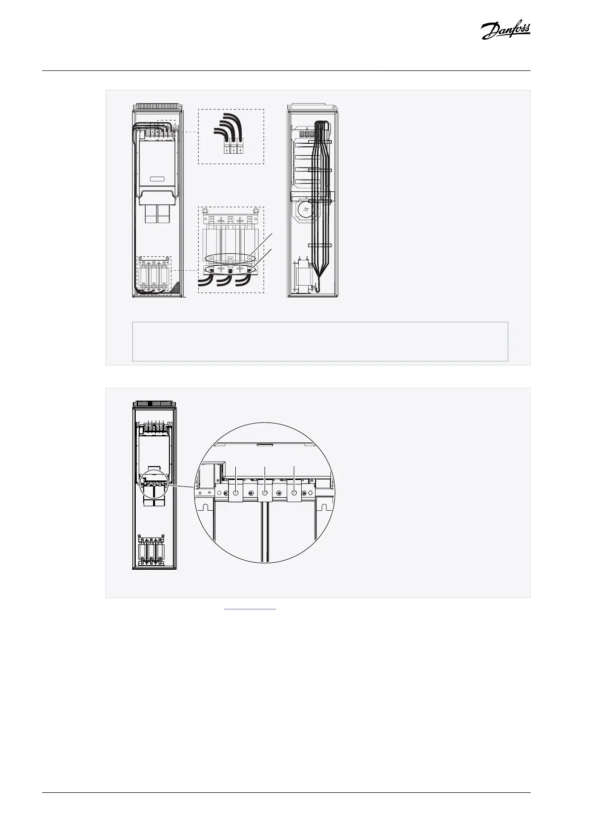
L1
L1 L2 L3
L2 L3
e30bj128.10
1
2
Illustration 31: Connecting the power cables between the AC choke and the power unit
Connect 3 motor cables to the output terminals U,V, and W of the power unit.
Illustration 32: Location of motor terminals, FR10/FR12
Connect the control cables. See 7 Control Unit for more information on control cables.
Attach the grounding conductor of each cable to the PE busbar.
AQ351737303996en-000201 / DPD0088858 | Danfoss A/S © 2023.09
Electrical Installation
VACON® NXP IP00 Drive Modules
Operating Guide

 Loading...


