6.
- a.
- b.
- c.
- d.
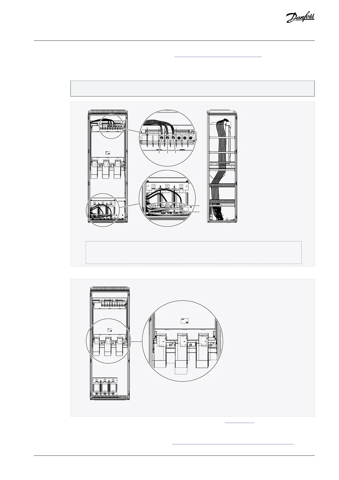
7.
Connect the cables. See the correct tightening torques in 12.8 Tightening Torques of the Terminals.
Connect 3 power cables to the output terminals of the AC choke and the input terminals of the power unit. It is
recommended to use cables designed for 90 °C (194 °F). Connect the L1 cable from the L1 terminal of the AC choke
to the L1 input terminal of the power unit, the L2 cable to the L2 terminal, and the L3 cable to the L3 terminal.
The AC choke has two sets of output terminals designed for different voltages/frequencies. Use the upper set for
500 V/50 Hz, 525 V/50 Hz, 600 V/60 Hz, and 690 V/50 Hz and the lower set for 400 V/50 Hz and 480 V/60 Hz.
Illustration 37: Connecting the power cables between the AC choke and the power unit, FR11
Connect 3 motor cables to the output terminals U, V, and W of the power unit.
Illustration 38: Location of motor terminals, FR11
Connect the control cables. For more information on control cables , see 7 Control Unit.
Attach the grounding conductor of each cable to the PE busbar.
Install input terminals on the installation plate and connect them to the input terminals (the uppermost terminals) of the
AC choke using busbars or flexible busbars according to 12.4.2 Busbar and Terminal Dimensions for 380–500 V AC and
AQ351737303996en-000201 / DPD00888 | 61Danfoss A/S © 2023.09
Electrical Installation
VACON® NXP IP00 Drive Modules
Operating Guide

 Loading...


