8.
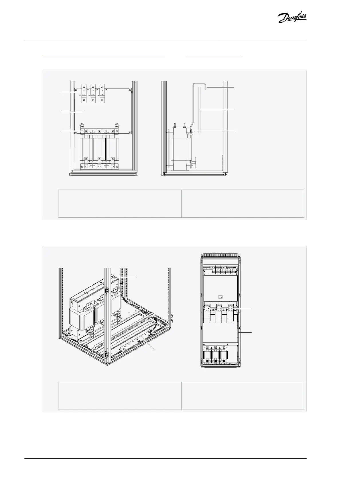
12.4.6 Busbar and Terminal Dimensions for 525–690 V AC. Also see 6.4 AC Choke Connections for information about AC
choke connections.
Illustration 39: Power Input Terminals and Busbars to AC Choke
Connect a grounding cable from the grounding connector at the lower right hand side of the power unit frame to the PE
busbar of the enclosure. Use a copper grounding cable with a cross-sectional area of at least 2*35 mm
2
per power unit,
which obeys the local regulations for grounding cables.
Illustration 40: Grounding the power unit, FR11
AQ351737303996en-000201 / DPD0088862 | Danfoss A/S © 2023.09
Electrical Installation
VACON® NXP IP00 Drive Modules
Operating Guide

 Loading...


