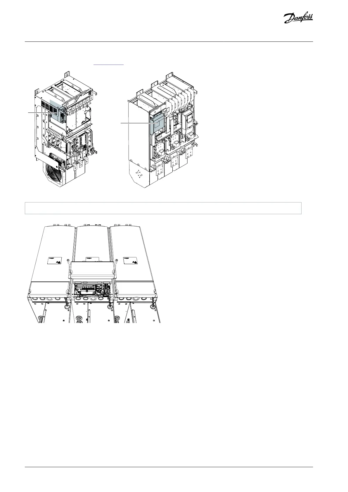
The control unit uses 24 V DC supplied from the ASIC board, which is on the left side of the power unit 1 in FR10–FR12, and in the
inverter unit in FR13–FR14 (see Illustration 62).
Illustration 61: Location of ASIC Board in FR10/FR11
Illustration 62: Location of ASIC Board in FR13–FR14
Each fiber optic cable has a number 1–8 and 11–18 (1–7 for FR10–FR11 and FR13) marked on the cable shield at both cable ends.
The list of the optic signals can be found in the following figures and table.
AQ351737303996en-000201 / DPD0088876 | Danfoss A/S © 2023.09
Control Unit
VACON® NXP IP00 Drive Modules
Operating Guide

 Loading...


