2
1
e30bh486.10
7 6 5 4 3 2 1
7 6 5 4 3 2 1
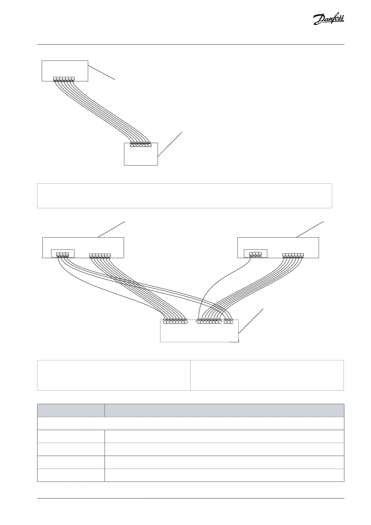
Illustration 63: Connections between the Optical Fiber Board and ASIC Board FR10–FR11, and FR13
Optical fiber board on control unit
3
1
2
e30bh490.10
T W V U
T W V U
W V U7 6 5 4 3 2 1T7 6 5 4 3 2 1T
7 6 5 4 3 2 1
7 6 5 4 3 2 1
Illustration 64: Connections between the Star-coupler Board, ASIC Boards, and Feedback Boards, FR12 and FR14
Power unit 1 (ASIC board and Feedback board)
Power unit 2 (ASIC board and Feedback board)
Star-coupler board on control unit
Table 22: Terminals on Optical Cable Adapter Board/Star-coupler Board, ASIC Boards, and Feedback Boards
ASIC board of Power unit 1/Power unit 2 (FR12 and FR14)
AQ351737303996en-000201 / DPD00888 | 77Danfoss A/S © 2023.09
Control Unit
VACON® NXP IP00 Drive Modules
Operating Guide

 Loading...


