3.
4.
5.
6.
7.
- a.
- b.
- c.
- d.
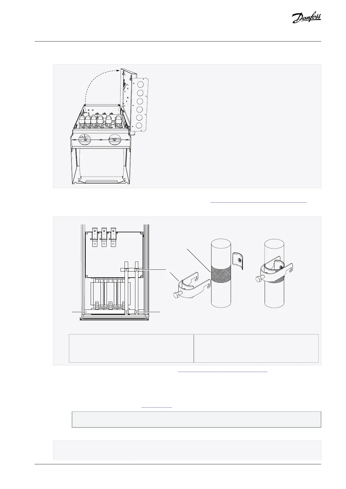
Open the power unit cover.
Pull the cable through the bottom plate of the cabinet and fix the PE conductor to the PE busbar of the cabinet.
Route the motor phase conductors through common mode chokes. See 6.5 Common-mode Chokes on Motor Cables.
To make a 360° connection with the grounding clamp for cable shield, expose the shield of motor cables.
Illustration 28: Installing EMC Grounding
Connect the cables. See the correct tightening torques in 12.8 Tightening Torques of the Terminals.
Connect 3 power cables to the input terminals of the power unit. It is recommended to use cables designed for 90
°C (194 °F). Connect the L1 cable to the L1 input terminal of the power unit, the L2 cable to the L2 terminal, and the
L3 cable to the L3 terminal.
Connect 3 motor cables to the output terminals U, V, and W of the power unit.
Connect the control cables. See 7 Control Unit for more information on control cables.
Make sure that the control cable wires do not come in contact with the electronic components of the unit or
control components inside the cabinet.
Attach the grounding conductor of each cable to the PE busbar.
AQ351737303996en-000201 / DPD00888 | 53Danfoss A/S © 2023.09
Electrical Installation
VACON® NXP IP00 Drive Modules
Operating Guide

 Loading...


