8.
X1 X1 X2 X3 X2 X3 X1 X1
2
3
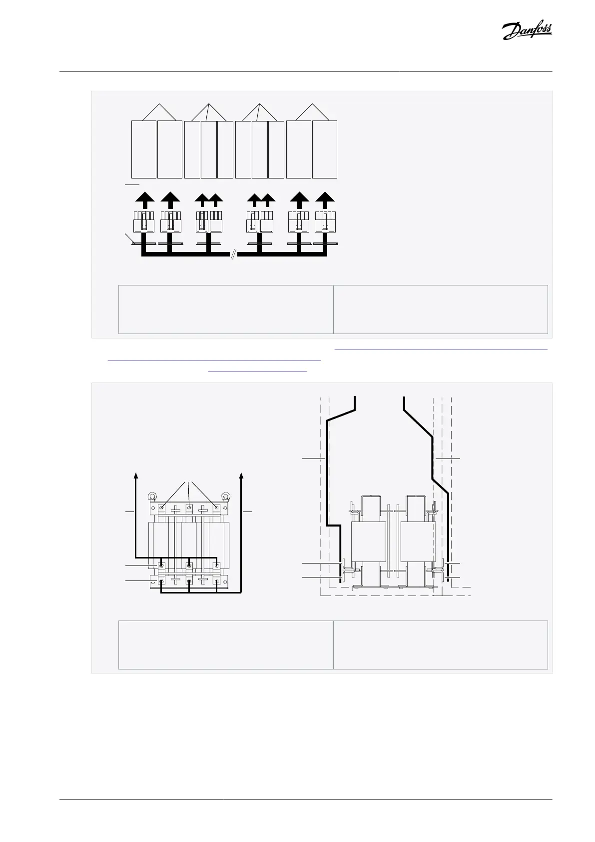
Illustration 48: FR14 with 4 NFE units
Route the incoming busbars to the AC chokes in the cabinet. See 12.4.2 Busbar and Terminal Dimensions for 380–500 V AC
and 12.4.6 Busbar and Terminal Dimensions for 525–690 V AC for the dimensions for the used busbars. Install a busbar on
each pole of the AC choke. See 6.4 AC Choke Connections for information about AC choke connections.
Illustration 49: Cabling from AC choke to NFE
Terminals for supply cables or busbars
AQ351737303996en-000201 / DPD00888 | 67Danfoss A/S © 2023.09
Electrical Installation
VACON® NXP IP00 Drive Modules
Operating Guide

 Loading...


