3.
4.
5.
6.
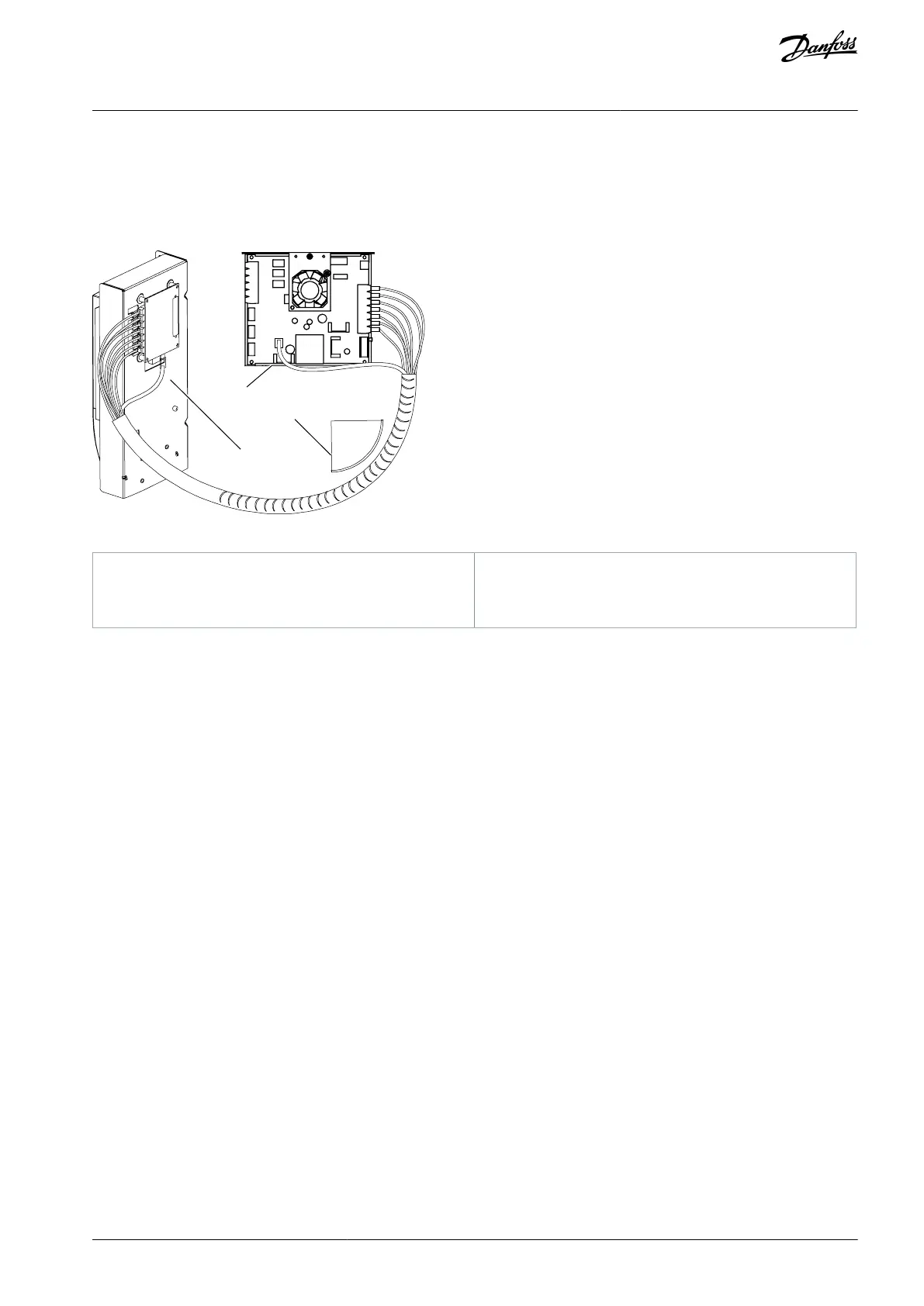
Connect each cable to the connectors marked with the same number on the ASIC board and on the rear side of the control
unit.
In FR12, connect the 4 fiber cables from the feedback boards to the star coupler board.
To prevent damages to the cables, attach the cable bundle at two or more points, at least once at each end.
Attach the cable cover on the power unit when the work is finished.
Illustration 65: Fiber Optic Cabling for FR10-FR11
Minimum bending radius 50 mm
AQ351737303996en-000201 / DPD00888 | 79Danfoss A/S © 2023.09
Control Unit
VACON® NXP IP00 Drive Modules
Operating Guide

 Loading...


