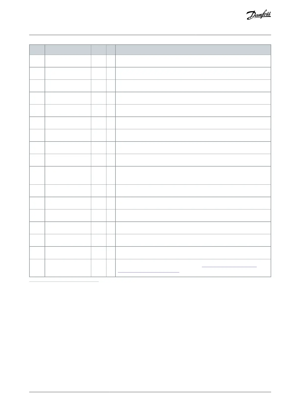
The output frequency to the motor
The frequency reference to motor control
The actual speed of the motor in rpm
The calculated shaft torque
The calculated motor shaft power in percentage
The output voltage to the motor
The measured voltage in the DC-link of the drive
The heat sink temperature in Celsius or Fahrenheit
The calculated motor temperature in percentage of the nominal temperature. See
VACON
®
All in One Application Manual.
Shows the status of the digital inputs 1–3
Shows the status of the digital inputs 4–6
Shows the status of the digital and relay outputs 1–3
Shows 3 monitored values to select from. See 8.7.6.9 Enabling/Disabling the
Change of Multimonitoring Items.
1
If the AC drive only has +24 V supply (for control board power-up), this value is not reliable.
See VACON
®
All in One Application Manual for more monitored values.
AQ351737303996en-000201 / DPD00888 | 85Danfoss A/S © 2023.09
Using the Control Panel
VACON® NXP IP00 Drive Modules
Operating Guide

 Loading...


